

 English
 русский
 عربى
 Español

YH-213 Brass Long-Handle Ball Valve with Double Female Threads and Union Design
Content
- 1 Product Overview
- 2 Key Technical Specifications
- 3 Dimensional Options
- 4 Advantages of the Union Design
- 5 Brass Body and Corrosion Resistance
- 6 ISO228 Parallel Thread Connections
- 7 Pressure and Temperature Performance
- 8 Applications
- 9 Long Handle and Visual Status Recognition
- 10 Manufacturing Strengths of the Supplier
- 11 Comparison with Conventional Fixed Threaded Valves
- 12 Installation Guidance
- 13 Leak Testing and Commissioning
- 14 Maintenance Recommendations
- 15 Safety Considerations
- 16 Purchasing and Project Selection
- 17 Why Manufacturing Quality Matters
- 18 Frequently Asked Questions
- 18.1 What is the main advantage of the YH-213 union design?
- 18.2 What does F/F mean?
- 18.3 What thread standard does the valve use?
- 18.4 What sizes are available?
- 18.5 What pressure can the YH-213 handle?
- 18.6 What is the working temperature range?
- 18.7 Can the valve be used for gas?
- 18.8 Can it be used for water?
- 18.9 Why is the handle yellow?
- 18.10 How should the union nut be tightened?
- 18.11 What should be done after reassembly?
- 18.12 Is the valve suitable for steam?
- 18.13 Why choose this valve instead of a conventional threaded ball valve?
- 19 Conclusion
- 20 References
- 21 Product: YH-213 Brass Valve(F/F)
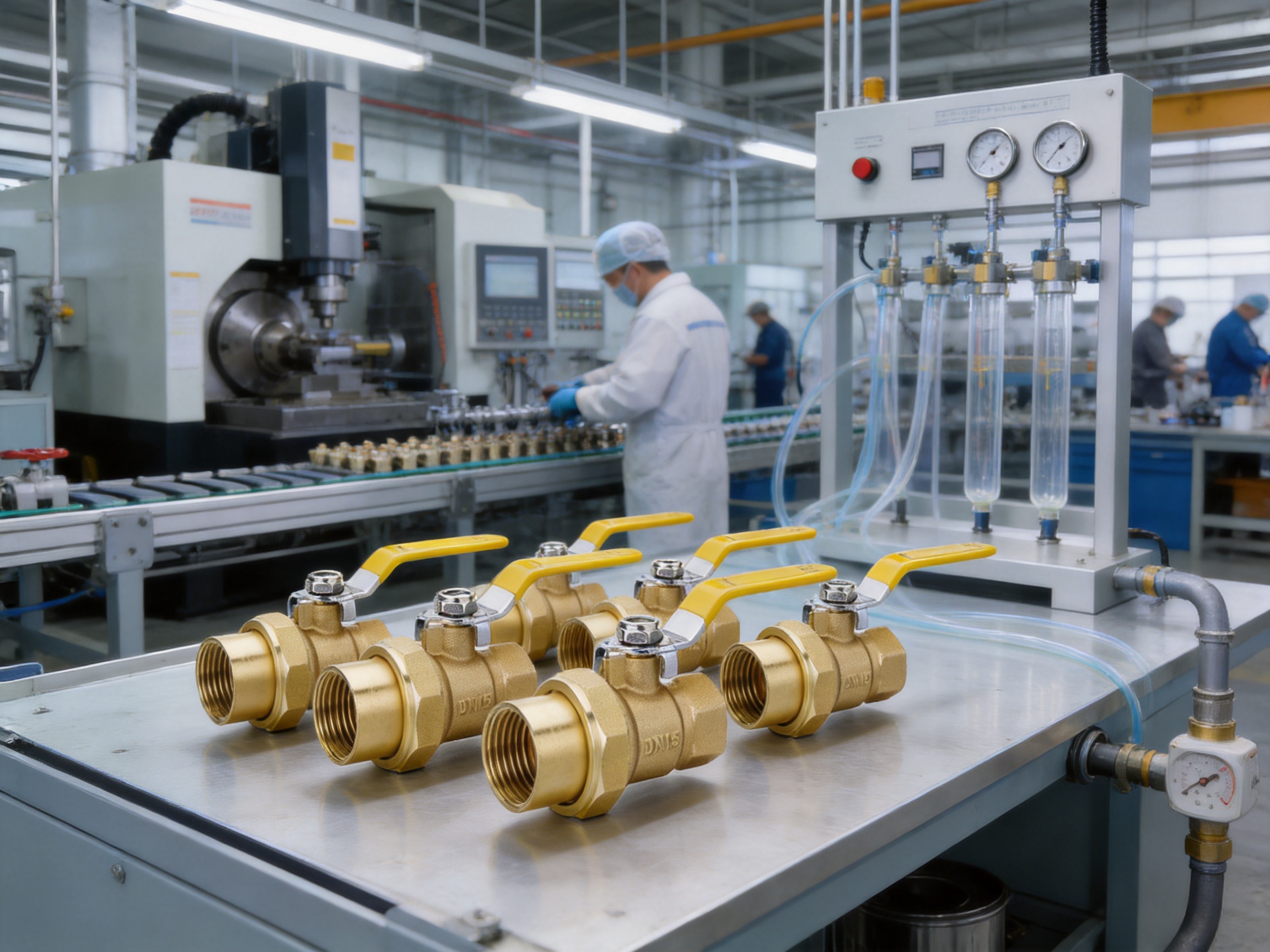
The YH-213 Brass Valve (F/F) is a compact, serviceable ball valve developed for gas appliance connections, meter branches, service points, and fluid pipelines that require convenient removal during maintenance. Its most important structural feature is the built-in union combined with double female-thread connections. This arrangement allows the valve body to be disconnected without cutting the pipeline or moving neighboring fittings, making installation and replacement substantially easier than with a conventional fixed threaded valve.
Manufactured by Ningbo Yunhua Valve Co., Ltd., the YH-213 combines a corrosion-resistant brass body, parallel pipe threads manufactured to ISO228 requirements, a long yellow handle, and a pressure rating of 1.6 MPa. The result is a practical valve for applications where reliable shutoff, simple visual identification, and repeated service access are important.
Compared with ordinary threaded ball valves, the YH-213 offers a more maintenance-oriented configuration. A traditional valve may need to be rotated out of a pipe assembly, which can disturb adjacent components or require substantial clearance. The union design separates this valve from the surrounding pipework, helping installers save time and reducing the possibility of damaging connected equipment during service.
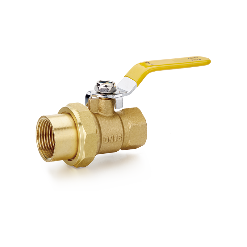
YH-213 Brass Valve(F/F)
Product Overview
The YH-213 is categorized as a brass long-handle ball valve with female/female, or F/F, threaded ends. Both inlet and outlet connections use female threads, allowing the valve to connect to male-threaded pipe ends, adapters, nipples, or other compatible fittings. The internal ball mechanism provides a direct shutoff function: when the bore in the ball aligns with the pipeline, the valve is open; when the ball turns approximately 90 degrees, the bore moves perpendicular to the flow path and the valve closes.
The long handle is designed to provide practical operating leverage and clear visual status recognition. Its yellow color makes the open or closed position easier to identify, which is particularly useful in equipment rooms, gas installations, service cabinets, and areas where multiple valves are installed close together.
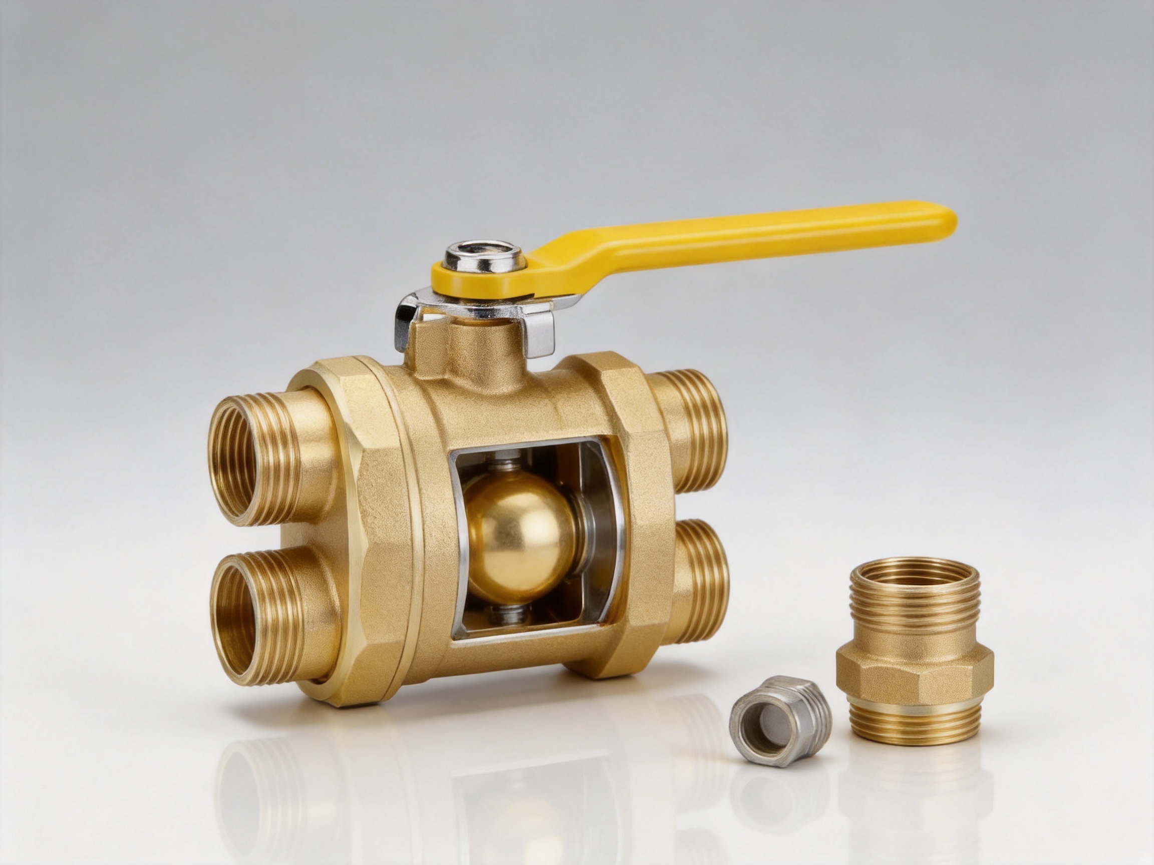
The built-in union is the defining feature of the YH-213 configuration. A union connection normally consists of a union nut, mating connection surfaces, and a sealing arrangement that permits the valve to be separated from the fixed pipeline. When the valve requires cleaning, inspection, replacement, or overhaul, the installer can close the line, release the union connection, and remove the valve body without dismantling the entire pipe run.
This design is especially valuable in confined spaces. Many service points are installed behind appliances, below meters, inside cabinets, or between rigid sections of pipe. In such locations, a standard threaded valve can be difficult to replace because the installer may not have enough space to rotate the valve or access the surrounding fittings. The YH-213 reduces this limitation by allowing separation through the union rather than requiring full rotational removal.
Key Technical Specifications
The principal specifications supplied for the YH-213 are summarized below. Actual installation should always be based on the valve marking, approved drawings, local regulations, and the confirmed requirements of the service medium.
| Item | Specification |
|---|---|
| Product model | YH-213 |
| Product type | Brass long-handle ball valve |
| Connection configuration | Female/female with built-in union |
| Nominal pressure | 1.6 MPa |
| Working temperature | -20°C to 80°C |
| Thread standard | Parallel pipe thread to ISO228 |
| Stated working media | Water, non-corrosive fluids, and gas, subject to application approval |
| Handle | Long yellow handle |
| Available nominal sizes | DN15, DN20, and DN25 |
The supplied product information identifies natural gas, artificial gas, and liquefied petroleum gas as working media in the product description. The dimensional information also lists water, non-corrosive fluids, and gas. This means that users should confirm the intended medium, seal compatibility, local code requirements, and purchasing specification before installation. A valve should never be used with a medium or under conditions outside its approved service range.
Dimensional Options
The YH-213 is available in three listed nominal sizes: DN15, DN20, and DN25. These correspond respectively to connection sizes of 1/2 inch, 3/4 inch, and 1 inch. The dimensions support selection according to the pipe size and the available installation space.
| Nominal Size | L | D | A | B | G |
|---|---|---|---|---|---|
| DN15 | 79 mm | 14 mm | 86 mm | 48 mm | 1/2 inch |
| DN20 | 85 mm | 17 mm | 90 mm | 51 mm | 3/4 inch |
| DN25 | 90 mm | 20 mm | 120 mm | 54 mm | 1 inch |
Dimension L generally represents the overall length of the valve assembly, while D, A, and B identify other product dimensions shown in the supplied drawing or dimensional schedule. G indicates the nominal thread size. Installers should compare these dimensions with the available cabinet, wall, meter, appliance, or equipment space before ordering.
Dimensional checks are particularly important when replacing an existing valve. A union valve may simplify removal, but the replacement must still have suitable end-to-end dimensions, thread size, handle clearance, and connection orientation. A small difference in length can affect pipe alignment, gasket compression, or the position of a connected appliance.
Advantages of the Union Design
Faster Valve Replacement
The most direct benefit of the union is faster replacement. With a fixed threaded valve, the installer generally has to rotate the valve out of the pipe or disconnect one or more adjacent fittings. This can be inconvenient when the pipe is rigid, when several components are close together, or when the opposite end of the assembly cannot be turned.
The YH-213 allows the valve to be isolated and separated at the union. The surrounding pipework can remain in position, reducing the number of components that need to be disturbed. This can shorten maintenance time and simplify work planning, particularly in commercial service installations where equipment downtime must be limited.
Reduced Disturbance to Existing Pipework
Every unnecessary disturbance to a pipe system creates additional opportunities for thread damage, seal damage, misalignment, and leakage. By allowing the main valve body to be detached without moving neighboring pipes, the YH-213 helps preserve the existing installation. This is an important advantage when the connected pipeline is old, difficult to access, or connected to sensitive equipment.
Reduced disturbance also helps maintenance teams avoid replacing several otherwise serviceable fittings simply because one valve has reached the end of its service life. In this way, the union arrangement can contribute to lower repair costs and more predictable maintenance procedures.
Improved Access in Confined Spaces
Service points are not always installed in open mechanical rooms. Valves may be located beneath kitchen equipment, inside meter boxes, behind boilers, within wall cabinets, or between closely spaced appliance connections. A fixed valve can be difficult to manipulate in such environments because the entire body must be rotated during installation or removal.
The union format is well suited to these conditions. Once the line is safely isolated and depressurized, the valve can be released from the union connection rather than rotated through a complete removal path. This provides a practical installation advantage where clearance is limited.
Support for Regular Inspection
Some applications require recurring inspection, cleaning, replacement, or functional checks. A valve that is difficult to remove may be left in service longer than recommended because maintenance is disruptive. The YH-213 makes planned servicing more manageable and can encourage a more systematic maintenance schedule.
The union does not eliminate the need for correct isolation procedures, but it can make the physical maintenance task more efficient after the system has been made safe. For gas applications, the line must be isolated, purged where required, and tested in accordance with applicable procedures before the union is opened.
Brass Body and Corrosion Resistance
Brass is widely used for compact valves because it combines mechanical strength, machinability, and resistance to atmospheric corrosion. The YH-213 brass body is designed for long-term service in common water, non-corrosive fluid, and gas applications within the specified pressure and temperature limits.
The material is also well suited to precision machining. Accurate internal passages, threaded connections, and sealing surfaces are essential for a ball valve. A brass body can be machined efficiently while maintaining the dimensional consistency needed for reliable assembly.
Corrosion resistance does not mean that every brass valve is suitable for every chemical service. The medium, concentration, temperature, contamination level, and operating cycle must be considered. The YH-213 is intended for the stated service categories, and users should obtain specific compatibility confirmation before applying it to aggressive chemicals, abrasive fluids, steam, oxygen service, or other specialized media.
The valve is not intended for steam service. Steam can involve temperatures and thermal conditions beyond the stated range, and its operation may impose requirements that differ significantly from those of water or gas. Keeping the application within the specified range is essential for maintaining safe performance.
ISO228 Parallel Thread Connections
The YH-213 uses parallel pipe threads to ISO228. A parallel thread connection is different from a tapered thread connection and should be installed using the correct sealing method. The thread itself is used to engage and align the components, while the seal is normally achieved through an appropriate gasket, sealing washer, union seal, or approved sealant at the designated sealing surface.
Using the wrong installation method can cause leakage or damage. Excessive force may deform a sealing element, distort a fitting, or damage the valve body. Insufficient tightening may prevent proper compression and allow leakage. Installers should use tools on the intended flats and avoid applying uncontrolled force to the handle or other non-load-bearing parts.
Thread cleanliness is also important. Dirt, metal chips, old sealant, and damaged thread fragments can prevent proper engagement. Before installation, the mating components should be inspected, cleaned, and checked for compatibility. The pipe should be properly supported so that the valve does not carry bending loads caused by unsupported pipework.
Pressure and Temperature Performance
The stated nominal pressure of the YH-213 is 1.6 MPa. This rating should be treated as a design limit for the defined service conditions, not as permission to operate continuously at any pressure under every possible temperature or medium. Actual performance can depend on fluid type, temperature, sealing materials, installation quality, and operating frequency.
The specified working temperature range is -20°C to 80°C. The valve should not be exposed to temperatures below or above this range during normal operation. Temperature can affect seal elasticity, pressure behavior, fluid viscosity, and the mechanical fit of the valve components.
Systems may experience pressure surges during rapid valve operation, pump starts, compressor cycling, or sudden changes in flow. The long handle makes operation convenient, but users should avoid unnecessarily abrupt actions where water hammer or gas system instability could result. The pipeline should be designed with suitable pressure control, relief measures, and support.
For gas installations, pressure testing and leak testing must follow the applicable local requirements. A valve that appears mechanically sound may still leak if the wrong sealant is used, if the union seal is damaged, or if the connection is not properly tightened.
Applications
Gas Appliance Connections
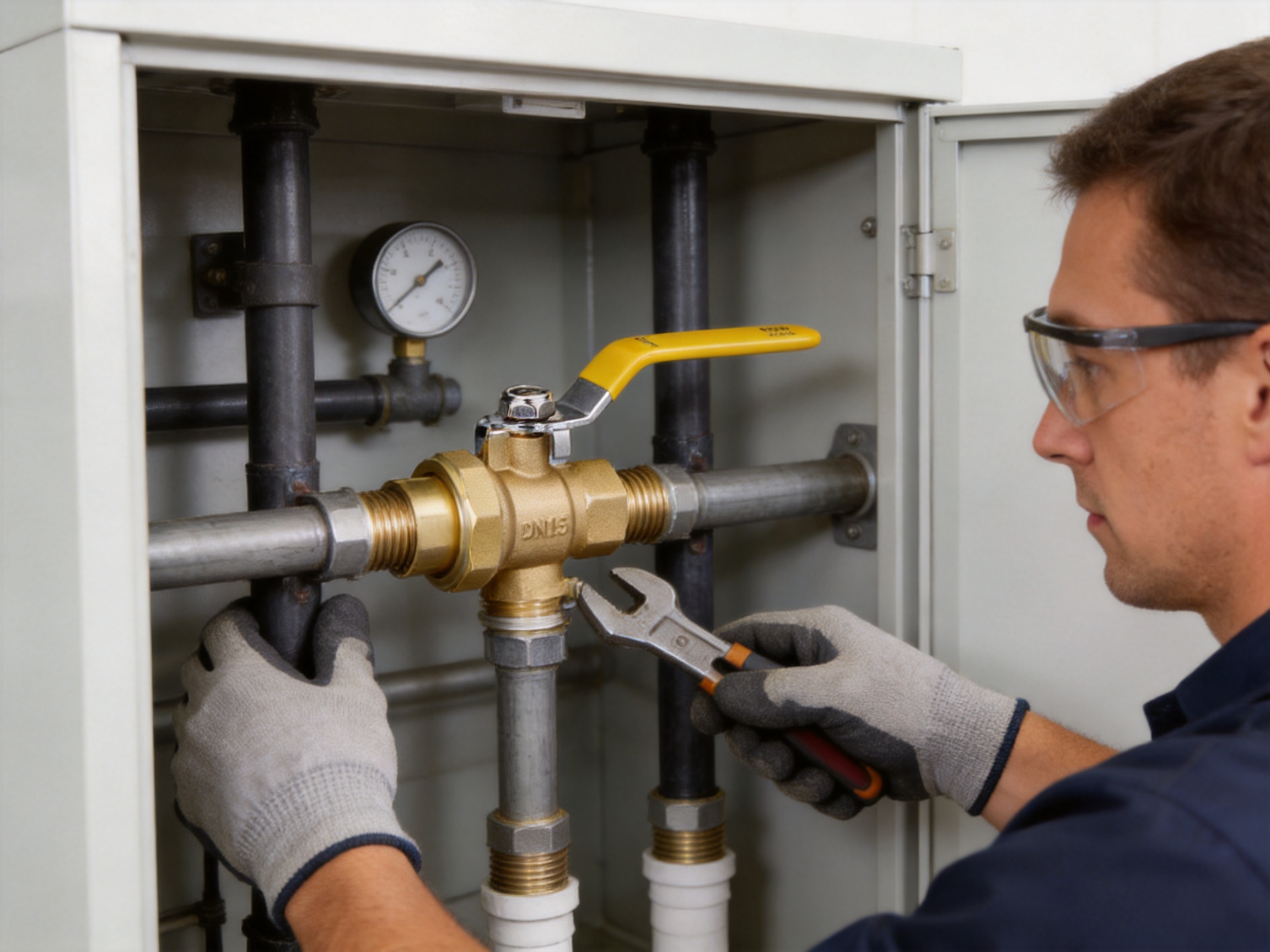
The YH-213 is suitable for selected gas appliance connections when the valve, sealant, pressure, temperature, and local installation requirements are compatible. Its yellow handle provides a clear visual indication and can help operators identify the shutoff position quickly.
Gas connections require special care because even a small leak can create a serious hazard. Only personnel qualified to work on gas systems should install or service the valve. The gas supply must be isolated before work begins, and a complete leak test must be carried out after assembly.
Meter Branches
Meter branches often require compact, clearly identifiable isolation points. The YH-213 can be used in suitable branch arrangements where the double female-thread configuration matches the pipework and the union provides a convenient service point. The valve may support future meter, regulator, or branch maintenance without requiring the complete surrounding pipeline to be dismantled.
Metering installations can be subject to utility company rules and regional technical standards. Product selection should therefore be coordinated with the responsible gas authority, equipment manufacturer, or project engineer.
Service Points
Service points are locations where equipment or sections of pipe may need to be isolated and removed. Examples include appliance branches, maintenance cabinets, compact utility assemblies, and fluid equipment connections. The YH-213 is valuable in these locations because its design anticipates future access rather than focusing only on initial installation.
Water and Non-Corrosive Fluids
The supplied information also identifies water and non-corrosive fluids as possible working media. In these applications, the valve can provide compact shutoff control for equipment branches, utility connections, and service lines, provided the pressure and temperature remain within the specified limits.
Fluid cleanliness should be considered. Particles may damage sealing surfaces or prevent the ball from closing smoothly. Where necessary, an upstream strainer or filter can help protect the valve from construction debris, rust particles, and other contaminants.
Long Handle and Visual Status Recognition
The long handle is a functional part of the product design. A ball valve normally requires a quarter-turn operation, and the handle position provides a quick indication of whether the valve is open or closed. The extended shape gives the operator a practical grip, even when wearing gloves or working in a moderately restricted space.
The yellow color improves visibility. In a crowded installation containing pipes, fittings, meters, and equipment, a bright handle can be identified more quickly than an unmarked or dark control. This can support faster response during inspection, isolation, and emergency procedures.
Handle visibility should not replace verification. Operators should understand the valve orientation and confirm the actual system condition when safety depends on isolation. If the handle is damaged, loose, or misaligned, the valve should be inspected before being relied upon.
Manufacturing Strengths of the Supplier
Ningbo Yunhua Valve Co., Ltd. is described as an enterprise specializing in the research, development, production, sales, and service of gas and fluid valves, water supply valves, and hardware accessories. Its manufacturing capabilities are an important part of the value proposition behind the YH-213.
The company operates a facility covering approximately 20,000 square meters and has developed a precision machining workshop, assembly line, and testing workshop. This type of organized production structure supports process control across multiple stages, from raw material machining to final valve testing.
The company’s reported annual production capacity includes approximately 2 million sets of valves and 10 million sets of hardware accessories. Such capacity can be advantageous for distributors, project contractors, equipment manufacturers, and OEM customers that require stable supply and repeatable product specifications.
Precision Machining
Ball valves depend on accurate machining. The body must maintain correct thread geometry, internal passage dimensions, ball alignment, and sealing surface relationships. The supplier reports the use of advanced domestic and international CNC machine tools. CNC machining can support repeatable dimensions and consistent production when supported by suitable tooling, inspection, and process management.
For the YH-213, precision machining is particularly relevant to the female-thread connections and union components. Properly produced threads help ensure smooth engagement with compatible fittings, while accurately machined sealing areas support dependable assembly.
Automated Assembly
Assembly quality affects the practical performance of every valve. Internal components must be installed in the correct order and orientation, seals must be positioned without damage, and the handle mechanism must operate smoothly. The supplier reports professional automated assembly equipment, which can help improve consistency and production efficiency.
Automation is most effective when combined with trained personnel, documented procedures, controlled component supply, and inspection checkpoints. A stable assembly process reduces variation between batches and supports the repeatability expected by professional buyers.
Testing Workshop
The supplier also reports a dedicated testing workshop. Valve testing is important because visual inspection alone cannot confirm pressure integrity or sealing performance. Depending on the production and customer requirements, testing may include body integrity checks, seat leakage checks, thread inspection, operational checks, and appearance inspection.
Testing should be performed using appropriate procedures and equipment for the valve type and rated service. Buyers requiring specific inspection records, sampling plans, or test documentation should define those requirements during quotation and order confirmation.
Integrated Production Capability
Research and development, machining, assembly, testing, sales, and service are all identified as parts of the supplier’s business. This integrated capability can make communication more efficient because product feedback, manufacturing concerns, and customer requirements can be coordinated within one organization.
For custom orders, a manufacturer with internal machining and assembly resources may be better positioned to discuss dimensional adjustments, packaging, labeling, handle colors, thread requirements, and application-specific production details. Any customization should be confirmed in technical drawings and written specifications before production.
Comparison with Conventional Fixed Threaded Valves
A standard fixed threaded ball valve can provide reliable shutoff when installed correctly, but it may be less convenient to remove. The valve body is connected directly to the surrounding pipework, and replacement commonly requires rotating the valve or disassembling an adjacent connection. This can be acceptable in an open installation with ample space, but it becomes difficult in compact service locations.
The YH-213 adds a union connection to the basic threaded ball valve format. This may slightly increase the number of components and the overall assembly length compared with a very simple fixed valve, but it provides a significant maintenance benefit. The choice should therefore be based on the full life-cycle requirement rather than initial purchase price alone.
| Evaluation Point | Conventional Fixed Threaded Valve | YH-213 Union Ball Valve |
|---|---|---|
| Valve removal | May require rotation or adjacent fitting removal | Can be separated at the union |
| Suitability for confined spaces | Dependent on rotational clearance | Designed to simplify removal in restricted areas |
| Maintenance access | Potentially disruptive | More convenient for replacement and overhaul |
| Connection type | Usually fixed threaded connections | Double female thread with built-in union |
| Visual identification | Depends on handle design and color | Long yellow handle for easy recognition |
| Typical value | Simple initial installation | Improved serviceability over the product life |
The YH-213 does not replace every possible valve design. A flanged valve, welded valve, press-connect valve, or specialized control valve may be more appropriate for a different system. Its advantage is specifically the combination of a compact ball-valve shutoff function, female threaded ends, and a removable union arrangement.
Installation Guidance
Before installation, confirm the valve model, nominal size, thread type, pressure rating, temperature range, and service medium. Check the pipeline for correct alignment and ensure that the valve is not being used to force two misaligned pipes together.
Inspect the threads, union surfaces, sealing elements, and valve body for damage. Remove dirt and debris from the connection points. Use only a sealant that is compatible with the intended medium and approved for the applicable gas or fluid service. For gas installations, use gas-grade sealing materials and follow local regulations.
Install the valve in the correct flow arrangement if the project documentation specifies one. Although many ball valves can operate in either flow direction, the complete assembly may include directional requirements or associated components that must be respected.
Support the pipework independently. The valve should not be used as a structural support or subjected to excessive bending, twisting, vibration, or impact. Tighten the connections using suitable tools and appropriate torque. Do not over-tighten the union nut, because excessive force may deform the seal or impair future disassembly.
After installation, operate the handle carefully to confirm smooth quarter-turn movement. Do not use a wrench, extension bar, or other tool on the handle unless a specifically approved procedure permits it. If the handle is difficult to move, investigate the cause rather than applying excessive force.
Leak Testing and Commissioning
Every newly installed or reassembled valve should be tested before being placed into service. For gas applications, a soap-bubble leak test is specifically recommended after reassembly, together with any pressure or tightness test required by local regulations. Apply the approved test solution to the relevant joints and observe for bubbles indicating leakage.
Never use an open flame to search for a gas leak. If leakage is found, isolate the supply, release pressure safely, correct the connection, and repeat the test. The union seal should be inspected if leakage occurs near the union nut or mating surfaces.
For water and non-corrosive fluid systems, pressurize the line gradually while checking the body, threads, union, and connected fittings. Sudden pressurization can create unnecessary stress and may make it more difficult to identify the source of a leak.
Commissioning should also verify the valve position, handle accessibility, labeling, and ability to isolate the intended section of pipeline. The valve should be left in the operating position specified by the system designer.
Maintenance Recommendations
The YH-213 is designed to reduce maintenance effort, but routine inspection remains important. Periodically check the body, union area, thread connections, handle, and visible sealing surfaces for corrosion, damage, leakage, or unusual movement.
Operate the valve periodically when permitted by the system owner and safety procedure. Regular operation can reveal stiffness or other changes before an emergency requires immediate shutoff. Do not cycle a valve if doing so could interrupt essential service or create an unsafe operating condition.
Keep the area around the valve accessible and free from stored materials. A highly visible handle is useful only if operators can reach it. Avoid painting over identification markings or obstructing the handle with insulation, cabinets, or temporary equipment.
When replacing the valve, use a new and compatible sealing element where required. Inspect the union mating surfaces and do not reuse damaged seals. Tighten the union nut correctly and carry out a full leak test after reassembly.
Safety Considerations
The YH-213 must be used within its rated pressure and temperature range. It should not be used for steam service or for media that are incompatible with the brass body, internal seals, or connection materials.
Gas work should be performed only by qualified personnel. Before opening a gas connection, isolate the supply and follow the required purging, ventilation, ignition-control, and testing procedures. The work area must be managed to prevent ignition sources and unsafe accumulation of gas.
For all media, pressure must be relieved before disassembly. A closed valve does not automatically prove that both sides of the valve are pressure-free. Trapped fluid or gas may remain in the valve body or adjacent piping. Confirm safe conditions before loosening the union.
The union nut must be tightened to the correct level. Over-tightening can deform the seal, damage the connection, or make later servicing more difficult. Under-tightening can permit leakage. The correct procedure should be determined by the installation standard, project instructions, and manufacturer guidance.
Purchasing and Project Selection
When specifying the YH-213, buyers should identify the required nominal size, thread size, medium, pressure, temperature, quantity, packaging, and documentation. DN15, DN20, and DN25 versions are listed, with 1/2-inch, 3/4-inch, and 1-inch connection sizes respectively.
Distributors should consider whether the union arrangement provides value for their target market. Plumbing contractors, gas service companies, appliance manufacturers, maintenance providers, and equipment assemblers may benefit from stocking a valve that is easier to remove in confined installations.
Project engineers should verify the complete dimensional envelope, including handle swing, union access, pipe clearance, and service access. The nominal pipe size alone does not guarantee that the valve will fit a specific cabinet or equipment assembly.
For OEM or private-label requirements, technical details should be confirmed before production. These may include handle color, markings, packaging, thread requirements, dimensional tolerances, inspection procedures, and delivery schedules. A written specification helps avoid misunderstandings between the purchaser, manufacturer, installer, and end user.
Why Manufacturing Quality Matters
A valve’s value is determined by more than its external appearance. Thread accuracy, internal surface condition, seal installation, operating torque, and pressure integrity all influence service performance. A manufacturer with dedicated machining, assembly, and testing resources is better positioned to control these factors systematically.
Ningbo Yunhua Valve Co., Ltd. reports a combination of CNC machining equipment, automated assembly and testing equipment, professional workshops, and substantial production capacity. These resources support the production of valves and hardware accessories for domestic and international customers while helping maintain consistent manufacturing processes.
The company’s stated mission is to build a safe fluid ecosystem with high-quality valves. For a product such as the YH-213, that objective is reflected in the emphasis on serviceability, clear operation, pressure capability, corrosion-resistant brass construction, and testing-oriented production.
Customers should still evaluate products according to their own quality requirements. Depending on the project, they may request material information, batch traceability, inspection records, sample approval, dimensional reports, or test documentation. Clear communication between the buyer and manufacturer is the best way to match production control with application risk.
Frequently Asked Questions
What is the main advantage of the YH-213 union design?
The built-in union allows the valve to be disconnected without cutting the pipe or moving neighboring fittings. This simplifies installation, replacement, cleaning, inspection, and overhaul, especially in confined spaces.
What does F/F mean?
F/F means female/female. Both ends of the valve have female threaded connections, allowing connection to compatible male-threaded pipe ends or fittings.
What thread standard does the valve use?
The YH-213 uses parallel pipe threads to ISO228. The correct sealing method must be used for a parallel-thread connection, and the mating fittings must be compatible.
What sizes are available?
The listed sizes are DN15, DN20, and DN25. Their corresponding connection sizes are 1/2 inch, 3/4 inch, and 1 inch.
What pressure can the YH-213 handle?
The stated nominal pressure is 1.6 MPa. The valve must be operated within the specified pressure and temperature limits, with consideration given to the actual medium and installation conditions.
What is the working temperature range?
The stated working temperature range is -20°C to 80°C. The valve is not intended for steam service or conditions outside this range.
Can the valve be used for gas?
The product information identifies natural gas, artificial gas, and liquefied petroleum gas as applicable media. Gas use must be confirmed for the specific installation, and gas-grade sealant, qualified installation, isolation procedures, and complete leak testing are required.
Can it be used for water?
The supplied technical information lists water and non-corrosive fluids as working media. Users should confirm pressure, temperature, fluid compatibility, and local requirements before installation.
Why is the handle yellow?
The yellow handle improves visibility and helps users recognize the valve position quickly. Operators should still verify the actual system condition whenever isolation is safety-critical.
How should the union nut be tightened?
The union nut should be tightened to the proper level specified by the applicable installation procedure. Over-tightening may deform the seal, while insufficient tightening may cause leakage. Do not use excessive force.
What should be done after reassembly?
After reassembly, inspect the connections and perform a complete leak test. For gas service, a soap-bubble test and any legally required pressure or tightness test should be completed before the installation is returned to service.
Is the valve suitable for steam?
No. The product information specifically states that the valve is not for steam service. Steam applications may exceed the rated temperature and require different valve materials and designs.
Why choose this valve instead of a conventional threaded ball valve?
The YH-213 provides the basic convenience of a quarter-turn brass ball valve while adding a union for easier removal. Its main advantage is reduced maintenance disruption, particularly where surrounding pipes cannot be moved or where installation space is restricted.
Conclusion
The YH-213 Brass Valve (F/F) is a practical solution for installations that require reliable shutoff together with future service access. Its built-in union allows the valve to be detached without disturbing neighboring pipework, while the double female-thread configuration supports common threaded connections. The brass body, ISO228 parallel threads, 1.6 MPa nominal pressure, -20°C to 80°C working range, and long yellow handle make the product suitable for a broad range of approved gas, water, and non-corrosive fluid applications.
Its competitive advantage is most apparent over conventional fixed threaded valves in confined spaces and maintenance-sensitive installations. Faster replacement, reduced pipe disturbance, improved access, and clear handle visibility can help lower service effort over the product life.
The supplier’s reported CNC machining resources, automated assembly equipment, dedicated testing workshop, extensive production capacity, and integrated valve manufacturing experience provide a strong manufacturing foundation. When combined with correct product selection, qualified installation, compatible sealing materials, proper union tightening, and complete leak testing, the YH-213 can provide a dependable and service-friendly valve solution for professional fluid control applications.
References
1. ISO 228, Pipe Threads Where Pressure-Tight Joints Are Not Made on the Threads.
2. General principles of brass valve design, machining, assembly, and pressure testing for threaded fluid-control products.
3. Product technical information for the YH-213 Brass Valve (F/F), including pressure, temperature, media, dimensions, and connection specifications.
4. Standard installation and leak-testing practices for threaded valves used in water, non-corrosive fluid, and gas systems.
5. Manufacturer-provided information concerning production facilities, CNC machining, automated assembly, testing workshops, production capacity, and company capabilities.
Product: YH-213 Brass Valve(F/F)

Related Products
-
 View More
-
 View More
YH-220 Full Port Brass Ball Valve with Long Handle(F/F)
-
 View More
YH-202 Brass Ball Valve with Long Handle(F/M)
-
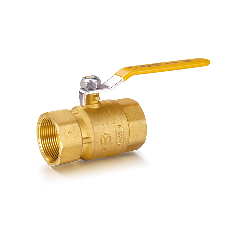 View More
YH-201 Brass Ball Valve with Long Handle(F/F)
-
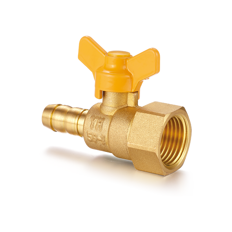 View More
YH-216 Brass Ball Valve with Butterfly Handle(F/Hose Connector)
-
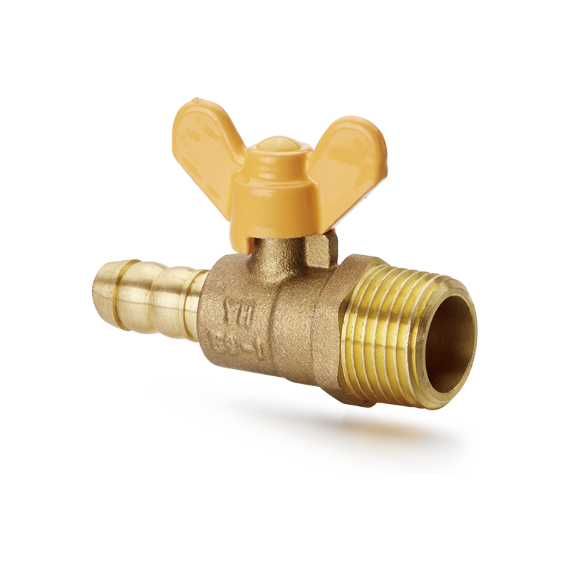 View More
YH-207 Brass Ball Valve with Butterfly Handle(M/hose connector)
Related News
Contact Us
-

-
 +86-0574-63742169
-
 No.104-128, Cizhang East Road, Zhangqi Town, Cixi City, Ningbo, Zhejiang Province, China


Message Us Now !
