

 English
 русский
 عربى
 Español

Magnetic Lockable Brass Ball Valve for Secure Gas Pipeline Control
Content
- 1 What Is a Magnetic Lockable Ball Valve?
- 2 Core Product Specifications
- 3 Access Control Through Magnetic Locking
- 4 Advantages of the Double Female-Thread Configuration
- 5 Brass Construction for Gas and Fluid Service
- 6 Manufacturing Strengths and Production Capability
- 7 How the YH-204 Compares with Ordinary Ball Valves
- 8 Comparison with Globe and Gate Valve Solutions
- 9 Applications in Gas Distribution Systems
- 10 Installation Guidance
- 11 Operating and Maintenance Practices
- 12 Quality Control from Machining to Final Testing
- 13 Project and Procurement Considerations
- 14 Safety Boundaries and Responsible Use
- 15 Frequently Asked Questions
- 15.1 What is the main purpose of the magnetic lock?
- 15.2 Can the valve be operated without the magnetic key?
- 15.3 What does F/F mean?
- 15.4 What thread standard does the valve use?
- 15.5 Which sizes are available?
- 15.6 What media can the valve handle?
- 15.7 What is the maximum working temperature?
- 15.8 What is the nominal pressure rating?
- 15.9 Is this valve suitable for throttling?
- 15.10 How should the valve be installed?
- 15.11 How can leakage be checked after installation?
- 15.12 What should be done if the magnetic lock does not work?
- 15.13 Why is the handle yellow?
- 15.14 What manufacturing capabilities support this product?
- 15.15 Can the valve be used outdoors?
- 16 Conclusion
- 17 References
- 18 Product: YH-204 Magnetic Lockable Ball Valve(F/F)
Gas distribution systems require more than simple on-and-off flow control. In residential buildings, commercial kitchens, utility networks, metering stations, and shared supply systems, a valve may need to perform two functions at the same time: it must regulate the passage of gas reliably, and it must prevent operation by unauthorised persons. The YH-204 Magnetic Lockable Ball Valve (F/F) is designed for this specific requirement. It combines a compact brass ball valve body, female-to-female threaded connections, ISO228 parallel pipe threads, and a magnetic locking mechanism that restricts handle operation to authorised users with the matching magnetic key.
This design provides a practical access-control solution for gas risers, meter outlets, branch pipelines, and other points where accidental or unauthorised valve operation could interrupt supply or create a safety concern. Instead of relying only on warning labels, protective cabinets, or ordinary handles, the valve adds a physical locking function directly to the operating mechanism. The result is a more controlled shut-off point that remains straightforward to install and easy for authorised personnel to operate.
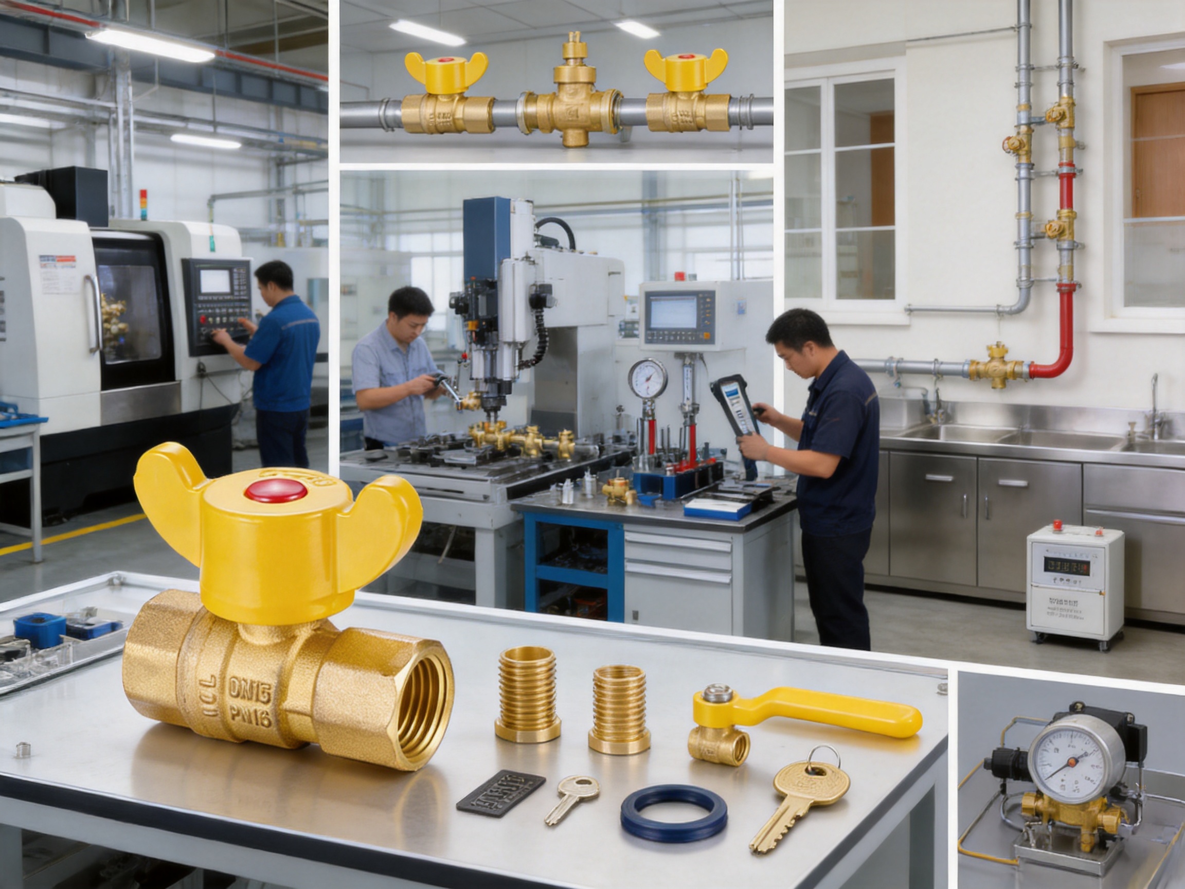
The valve is manufactured by Ningbo Yunhua Valve Co., Ltd., an enterprise focused on gas and fluid valves, water supply valves, and hardware accessories. Its production capabilities include precision machining, automated assembly, and testing operations supported by CNC machine tools and professional inspection equipment. These manufacturing strengths are important because a lockable valve must provide both mechanical reliability and consistent operating performance. A magnetic lock is useful only when the body, ball, stem, threads, seals, and operating mechanism are produced with suitable accuracy and assembled correctly.
What Is a Magnetic Lockable Ball Valve?
A magnetic lockable ball valve is a quarter-turn valve equipped with a locking system that controls access to the handle. In a conventional ball valve, the handle can normally be rotated by anyone who can reach it. In a magnetic lockable model, the internal locking structure keeps the handle secured until a compatible magnetic key is applied. Once the key releases the mechanism, the authorised user can rotate the handle to open or close the valve.
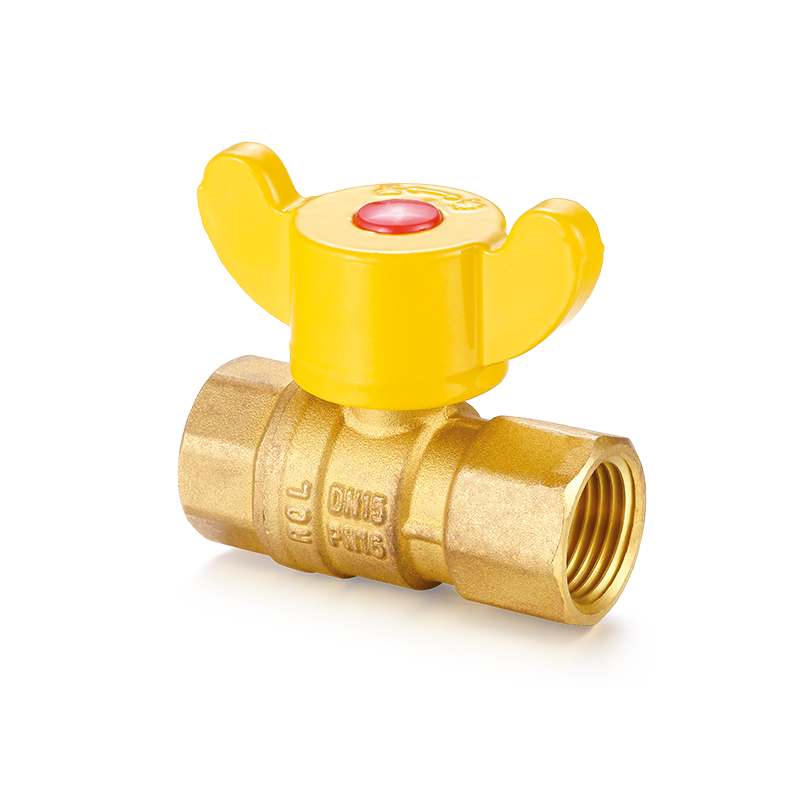
The YH-204 uses a brass valve body and a double female-thread configuration. The F/F arrangement means that both ends of the valve have internal threads. This allows it to connect directly with standard male-threaded pipe ends, nipples, adaptors, or other compatible pipeline components. Its parallel pipe thread follows ISO228, supporting installation in systems designed around that thread standard.
Ball valves are widely selected for isolation service because the internal ball normally provides a direct flow passage when the valve is open. A quarter-turn movement changes the ball position from open to closed, making the valve faster to operate than a multi-turn gate or globe valve. The YH-204 adds access control to this familiar operating concept, making it suitable for locations where the ability to turn the valve must be limited.
The valve is intended for natural gas, artificial gas, liquefied petroleum gas, water, and other non-corrosive fluids within the stated service conditions. For any specific installation, the user should confirm that the medium, pressure, temperature, sealing materials, and applicable local requirements are suitable. Gas installations should always be carried out and inspected by qualified personnel according to local regulations.
Core Product Specifications
The YH-204 is available in two commonly used nominal sizes: DN15, corresponding to 1/2 inch, and DN20, corresponding to 3/4 inch. These sizes are frequently used in gas risers, meter connections, branch lines, and compact utility installations. The rated nominal pressure is 1.6 MPa, while the stated working temperature range is from -20°C to 80°C.
| Item | DN15 | DN20 |
| Nominal size | 1/2 inch | 3/4 inch |
| Thread type | ISO228 parallel female thread | ISO228 parallel female thread |
| Nominal pressure | 1.6 MPa | 1.6 MPa |
| Working temperature | -20°C to 80°C | -20°C to 80°C |
| Connection configuration | Female-to-female | Female-to-female |
| Dimension G | 1/2 inch | 3/4 inch |
| Dimension D | 12 mm | 18 mm |
| Dimension L | 55 mm | 66 mm |
| Dimension A | 43.5 mm | 48 mm |
The compact dimensions make the valve suitable for installations where space is limited. The DN15 model has a listed overall length of 55 mm, while the DN20 model has a listed overall length of 66 mm. Before ordering, installers should compare the dimensions with the available pipeline space, the position of adjacent fittings, and the required clearance for using the magnetic key.
The bright yellow protective handle provides clear visual identification. In many utility environments, colour coding helps operators recognise the valve quickly, especially when multiple fittings are installed close together. The handle position can also provide a visual indication of the valve status, although the exact interpretation should follow the installation practice and operating instructions used by the facility.
Access Control Through Magnetic Locking
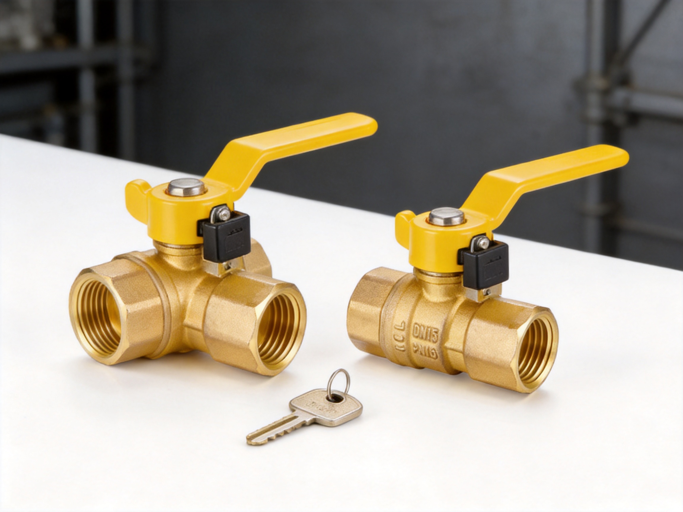
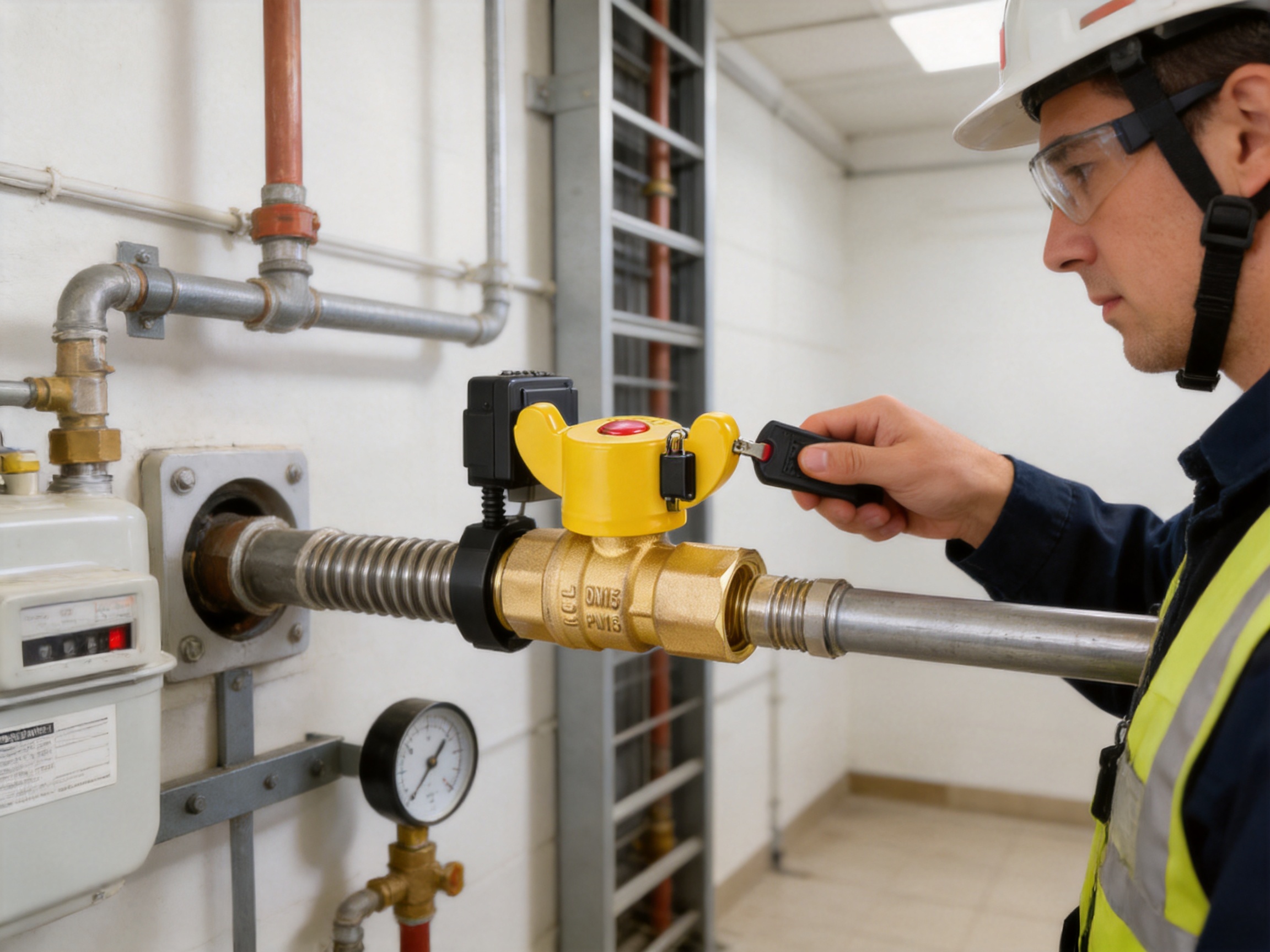
The principal advantage of the YH-204 is its magnetic locking function. The internal magnetic structure prevents ordinary handle rotation until the matching magnetic key is used. This creates a controlled operating point without requiring a separate padlock, chain, external enclosure, or custom locking bracket.
This feature is especially useful in multi-user gas systems. A valve installed on a shared riser, meter outlet, or branch pipeline may be accessible to residents, kitchen staff, maintenance workers, visitors, or members of the public. Not every person near the valve should be able to change its position. Unauthorised closure can interrupt gas service, while unauthorised opening may create a safety risk if downstream appliances or equipment are not ready for operation.
Compared with a standard ball valve, the magnetic version provides an additional layer of control. A conventional handle can often be turned immediately by hand. A padlockable handle may offer better security, but it requires a separate lock and may take more space. A valve installed inside a protective box can also restrict access, but the box may complicate inspection, ventilation, maintenance, or emergency operation. The integrated magnetic mechanism is a compact alternative for installations that need controlled access while retaining a familiar quarter-turn valve format.
The magnetic lock is not intended to replace good operating procedures, warning signs, gas detection systems, pressure regulation, or professional inspection. It is a mechanical access-control feature. Its function is to stop casual or unauthorised operation of the valve handle. Safe gas system design must still consider pressure control, pipe sizing, ventilation, appliance condition, emergency shut-off arrangements, and local codes.
Each installation should maintain control over the magnetic key. The key should be stored securely and made available only to authorised operators or qualified maintenance personnel. If a key is lost, the locking structure should not be forced, drilled, struck, or dismantled by unqualified staff. The appropriate approach is to contact the supplier with the valve model and relevant identification information to obtain a compatible replacement or approved service solution.
YH-204 Magnetic Lockable Ball Valve(F/F)
Advantages of the Double Female-Thread Configuration
The F/F construction gives the YH-204 a practical advantage in many threaded pipeline layouts. Both valve ends contain internal threads, allowing connection to male-threaded pipe fittings on either side. This configuration can simplify procurement because installers can use commonly available nipples, male adaptors, riser fittings, or threaded pipe ends that match the required size.
A double female-thread valve can also make replacement work more flexible. When an existing installation includes male-threaded connections, the valve may be fitted without redesigning the entire branch line. This is useful during maintenance or renovation projects where the objective is to replace an ordinary shut-off valve with a controlled-access model while keeping the surrounding pipework substantially unchanged.
ISO228 parallel threads support compatibility with systems that use parallel pipe thread connections. However, installers should distinguish between thread form and sealing method. A parallel thread does not automatically provide sealing at the thread flanks in the same way as some tapered thread systems. The correct gasket, sealing washer, O-ring arrangement, or approved thread sealant must be used according to the valve design and the installation standard. Gas-approved sealing materials should always be selected for gas service.
The internal-thread arrangement also gives the valve a clean and compact external profile. There are no flanged bolt circles, large connection faces, or extended welded ends. This makes it suitable for small-diameter lines and confined service spaces. The installer should nevertheless avoid excessive pipe loading. The valve should be supported by the pipeline or suitable brackets so that bending forces, vibration, or misalignment do not transfer excessive stress to the body.
Brass Construction for Gas and Fluid Service
Brass is widely used for compact valves because it combines useful mechanical strength, machinability, corrosion resistance in many ordinary environments, and suitability for threaded components. It can be precision-machined to create accurate internal passages, thread profiles, stem seats, and sealing surfaces. For a small valve used in building services, the material provides a practical balance between durability, cost, weight, and manufacturing efficiency.
The brass body of the YH-204 is suitable for the stated applications involving natural gas, artificial gas, liquefied petroleum gas, water, and other non-corrosive fluids, subject to the specified pressure and temperature limits. Brass should not be treated as universally compatible with every chemical or process medium. Media containing aggressive chemicals, abrasive solids, or unusual contaminants may require a different body material or seal arrangement. Engineering review is recommended whenever the valve is used outside ordinary building gas and water services.
A brass body can also support reliable threaded assembly when the threads are produced accurately and handled correctly. During installation, the use of suitable tools and correct tightening practices is essential. Wrenches should be applied to the appropriate body flats or connection areas rather than the magnetic housing or handle. Excessive torque can deform threads, damage seals, or place unnecessary stress on the valve body.
Material selection is only one part of product quality. The precision of machining, cleanliness during assembly, seal installation, ball and stem alignment, and final testing all influence service performance. This is why the manufacturing system behind the valve is an important part of its value proposition.
Manufacturing Strengths and Production Capability
Ningbo Yunhua Valve Co., Ltd. specializes in the research, development, production, sales, and service of gas and fluid valves, water supply valves, and hardware accessories. The company has developed its operations over more than ten years, establishing a management system and production structure intended to support repeatable manufacturing.
The company operates on an area of approximately 20,000 square meters and has developed a precision machining workshop, an assembly line, and a testing workshop. These dedicated production areas allow different stages of valve manufacturing to be organised according to their function. Precision machining focuses on dimensional accuracy. Assembly focuses on correct component placement and operating performance. Testing focuses on verification before products are released.
The production system is supported by domestic and international CNC machine tools. CNC equipment is valuable in valve production because it can maintain consistent dimensions across repeated batches. Accurate machining is particularly important for the YH-204 because the valve includes threaded ends, a ball passage, stem interfaces, sealing surfaces, and a magnetic locking mechanism. Variations in any of these areas can influence installation quality or operating feel.
Automated assembly and testing equipment can further improve production consistency. Manual skill remains important, but automated or semi-automated processes can help control assembly sequences, reduce variation, and improve production efficiency. For a valve with a controlled-access mechanism, the assembly process must ensure that the magnetic lock interacts correctly with the handle and that the valve can only be operated with the intended key.
The company reports an annual production capacity of approximately 2 million sets of valves and 10 million sets of hardware accessories. This scale supports ongoing supply for distributors, contractors, equipment manufacturers, and project purchasers. Capacity alone does not guarantee suitability for a particular project, but it can provide practical benefits such as repeat-order support, product continuity, and the ability to handle larger procurement programs.
A professional testing workshop is also significant for gas valve production. Testing may include visual inspection, dimensional verification, thread inspection, operating checks, and pressure or leakage checks appropriate to the product and applicable requirements. Buyers should confirm the exact inspection records, test standards, certificates, and approvals required for their market and application.
How the YH-204 Compares with Ordinary Ball Valves
The most direct comparison is with a conventional brass ball valve that has a standard lever handle. Both valve types can provide quarter-turn isolation, compact installation, and relatively quick operation. The difference is that the ordinary valve generally remains accessible to anyone who can reach the lever, while the YH-204 introduces magnetic access control.
In a private mechanical room with restricted entry, an ordinary valve may be sufficient. In a shared residential building, public utility area, commercial kitchen, or meter cabinet accessible to multiple users, unauthorised operation is a more realistic concern. In these environments, the magnetic lock can provide a meaningful functional advantage without changing the basic operating principle of the valve.
The YH-204 may also reduce the need for separate lockout accessories. A separate padlockable handle can be effective, but the purchaser must select and manage the padlock, ensure that it fits, and provide enough clearance for the lock body and shackle. The magnetic system is integrated into the valve and is intended to preserve a compact profile.
Another advantage is visual simplicity. The yellow handle is easy to identify, while the absence of an external padlock can create a neater appearance in meter assemblies and compact pipe cabinets. The valve remains recognisable as a shut-off device while its operating access is controlled.
These advantages should be evaluated against the operating policy of the facility. If emergency responders or multiple service teams may need immediate access, the organisation must maintain an accessible procedure for obtaining the correct magnetic key. A locking system is beneficial only when authorised operation remains practical.
Comparison with Globe and Gate Valve Solutions
Globe valves are commonly used where throttling or flow regulation is required, but they generally require multiple turns to move between open and closed positions. Their bodies may also be larger and create a higher flow restriction when fully open, depending on the design. For simple isolation in a small gas branch, a ball valve offers a faster quarter-turn action and a compact form.
Gate valves are also used for isolation, particularly in larger pipelines. However, their multi-turn stems and larger installation envelope may not be necessary for small building-service connections. The YH-204 is designed around DN15 and DN20 threaded applications, where a compact quarter-turn valve can be easier to operate and maintain.
A globe or gate valve can sometimes be fitted with an external locking accessory, but access control may require additional hardware or a custom arrangement. The YH-204 integrates the magnetic locking function into the operating design. This makes it a purpose-built choice for controlled shut-off rather than a general valve adapted after installation.
The YH-204 should not be selected as a replacement for a regulating valve when precise flow control is required. Ball valves are primarily isolation devices. Keeping the valve partially open for continuous throttling may cause undesirable flow conditions, noise, wear, or reduced service life unless the manufacturer specifically approves that operating mode.
Applications in Gas Distribution Systems
One important application is the gas riser in a residential or mixed-use building. A riser may serve multiple apartments or separate user areas. A magnetic lockable valve can be installed at an appropriate isolation point so that building management or authorised gas service personnel can control the supply while reducing the risk of casual operation by residents.
Another application is the meter outlet. Meter assemblies often contain several fittings in a confined area, and unauthorised access may interfere with billing, maintenance, or safe operation. A lockable valve can help distinguish the authorised control point and limit operation to trained personnel.
Commercial kitchens may also benefit from controlled shut-off. Kitchens can have multiple staff shifts, contractors, cleaning teams, and delivery personnel. A magnetic lock can reduce the likelihood that someone unfamiliar with the system will operate the gas isolation valve without checking appliances, ventilation, or restart procedures.
Branch pipelines in public or semi-public utility systems are another suitable application. Where a branch supplies a group of users or equipment, a controlled-access valve can support maintenance planning and reduce accidental interruptions. The compact size of the DN15 and DN20 versions makes them appropriate for small branch connections where larger valve assemblies would be unnecessary.
In all these applications, the valve should be installed in a location that is accessible to authorised personnel, protected from impact, and clearly identified. The magnetic lock should not be buried, enclosed without access, exposed to conditions beyond its specification, or positioned where the key cannot be applied properly.
Installation Guidance
Before installation, confirm the nominal size, thread type, flow direction requirements if any, available length, handle clearance, medium, pressure, temperature, and local code requirements. Inspect the valve for visible damage and verify that the threads are clean. Do not install a valve with damaged threads, a deformed handle, or a locking mechanism that does not function correctly during an initial check.
Make sure the pipeline is depressurised and free from hazardous gas before beginning work. Gas installation should be performed by qualified professionals. The line should be clean enough to prevent excessive debris from entering the valve. Metal chips, scale, sealing material, or construction particles can interfere with the ball, seats, or stem.
Use only a sealant or sealing tape approved for the intended gas or fluid service. Apply the sealant carefully so that excess material does not enter the flow passage. Excessive sealant inside a threaded connection can migrate into the valve and affect operation. The sealing method must also be compatible with ISO228 parallel threads and the specific connection arrangement.
Align the valve with the pipe without forcing the body into position. Cross-threading can damage the valve and the mating fitting. Tighten the connection with suitable tools and controlled force. Do not use the magnetic handle, magnetic housing, or key interface as a place to apply installation torque. If the pipeline requires significant force to align, correct the pipe support or fitting position rather than forcing the valve.
After installation, operate the valve using the matching magnetic key. Confirm that the handle remains locked when the key is absent and that it turns smoothly when the key is correctly applied. Check the open and closed positions according to the system procedure. The handle should not be forced beyond its intended travel.
A leak test must be completed before the system is placed into service. For gas service, use an appropriate approved testing method, such as a soap-bubble solution where permitted by local procedures, and inspect all threaded joints and valve interfaces. Never use an open flame to search for gas leakage. If leakage is found, depressurise the system, correct the connection, and repeat the test.
Following the leak test, confirm that downstream appliances and equipment are ready before restoring supply. The valve should not be opened simply because the pipeline has passed a pressure or leakage check. The complete system must be prepared for safe operation.
Operating and Maintenance Practices
The magnetic key should be stored in a secure but accessible location known to authorised operators. Facilities may choose to maintain a key register, especially where several valves or buildings are involved. The key should be kept clean and protected from unnecessary impact, moisture, and loss.
Operators should avoid using unapproved magnetic objects or improvised tools. A non-matching object may fail to release the lock and could damage the interface. If the correct key does not operate the mechanism, check that it is aligned correctly and that the handle is not under excessive pipeline stress. Do not strike or twist the key with excessive force.
Periodic inspection should include visual examination of the brass body, threaded joints, yellow handle, and magnetic locking area. Look for corrosion, impact marks, leakage, unusual looseness, contamination, or signs of unauthorised tampering. The valve should be operated periodically according to the facility maintenance plan, provided that operation can be performed safely and without disrupting essential service.
Do not paint over the handle, lock interface, or identifying marks. Coatings or dirt may interfere with the magnetic key or make the valve status difficult to identify. If the valve is installed outdoors or in a damp environment, the installation should provide suitable protection from standing water, severe contamination, and mechanical damage.
The maximum stated working temperature is 80°C. The valve is not suitable for steam service or for media outside the specified application range. Temperature, pressure, and chemical compatibility must remain within the design limits throughout operation, including abnormal but foreseeable conditions.
Quality Control from Machining to Final Testing
Reliable valve production begins with control of incoming materials and components. Brass material, sealing elements, stems, balls, handles, and magnetic components must be suitable for the product design. Consistency in material and component dimensions helps reduce variation during machining and assembly.
During CNC machining, the valve body can be produced with controlled external dimensions, internal passages, and thread geometry. Accurate threads improve connection quality and reduce the risk of leakage caused by poor engagement. The ball cavity and stem interface must also be machined so that the ball rotates properly and the seals seat correctly.
Assembly requires attention to the order and condition of internal components. Seals must be installed without cuts or distortion. The ball and stem must be correctly aligned. The handle must transmit quarter-turn movement without excessive play. The magnetic locking components must be positioned so that the handle remains secured when the key is not present and releases when the correct key is applied.
Testing provides the final opportunity to identify problems before shipment. Depending on the applicable product control plan, testing may include pressure holding, leak inspection, operating torque checks, lock function checks, thread inspection, and appearance review. The exact tests and acceptance criteria should be confirmed with the manufacturer for a particular purchase order or regulated market.
The combination of CNC machining, automated assembly, and a dedicated testing workshop provides a foundation for repeatable product quality. It also helps the manufacturer respond to customer requirements involving dimensions, packaging, batch control, and project quantities. For distributors and original equipment manufacturers, stable production processes can be as important as the individual valve specification.
Project and Procurement Considerations
When selecting the YH-204, purchasers should first determine whether DN15 or DN20 is appropriate for the pipeline. The valve size should match the actual connection and required flow capacity, not simply the size of a nearby fitting. Flow requirements, pressure loss, appliance demand, and local design standards should be reviewed by the responsible engineer or installer.
The purchaser should also confirm whether the project requires specific gas approvals, certificates, inspection documents, traceability, or national standards. Product information states the pressure, temperature, medium, and thread characteristics, but regional regulations may impose additional requirements. The manufacturer can provide the relevant documentation available for the intended market and production batch.
For larger projects, buyers may request samples, dimensional drawings, packaging details, key management arrangements, and replacement-key procedures. If multiple valves are installed in one facility, it is useful to clarify whether one key is intended to operate all matching valves or whether different key configurations are available. The access-control policy should be agreed before installation.
Packaging should protect the threaded ends, handle, and magnetic mechanism during transport. Thread protectors can help prevent damage and contamination. On receipt, the purchaser should inspect cartons and products, record any damage, and store valves in a clean, dry area until installation.
Supply continuity is another consideration. A manufacturer with substantial annual production capacity and established machining, assembly, and testing facilities can support repeat orders more effectively than a supplier relying entirely on irregular outsourced production. Ningbo Yunhua Valve Co., Ltd. reports an annual capacity of 2 million valve sets and 10 million hardware accessory sets, providing a production base for regular commercial supply.
Safety Boundaries and Responsible Use
A lockable valve is a component within a larger gas or fluid system. It cannot correct incorrect pipe sizing, defective appliances, poor ventilation, inadequate pressure regulation, or unsafe installation practices. The magnetic lock limits access to the handle, but it does not detect leakage or automatically shut off the system in response to abnormal conditions.
Users must respect the stated service limitations. The nominal pressure is 1.6 MPa, and the working temperature range is -20°C to 80°C. The valve is not intended for steam or unspecified aggressive media. If the system may experience pressure surges, extreme temperature, vibration, or chemical exposure, the application should be reviewed before installation.
Emergency procedures should account for the magnetic key requirement. Authorised personnel must know where the key is stored and how to operate the valve. In facilities with multiple shifts, key availability and training should be included in the operating plan. The key must never be hidden in a location that delays a necessary authorised shut-off.
If a valve becomes difficult to operate, leaks, or shows physical damage, it should be removed from service or inspected by qualified personnel. Do not attempt to repair the locking mechanism with unapproved parts. Do not bypass the lock by removing the handle or applying excessive force. A controlled replacement or supplier-supported service procedure is safer and more reliable.
Frequently Asked Questions
What is the main purpose of the magnetic lock?
The magnetic lock prevents ordinary or unauthorised handle operation. The handle can be rotated only after the matching magnetic key releases the internal locking mechanism. This is useful for shared gas systems, meter outlets, utility areas, and other locations where access must be controlled.
Can the valve be operated without the magnetic key?
The valve is designed not to operate normally without the matching magnetic key. Users should not attempt to force the handle or use improvised tools. If the key is lost, contact the supplier with the model information to request an appropriate replacement solution.
What does F/F mean?
F/F means female-to-female. Both ends of the valve have internal threads, allowing connection to compatible male-threaded pipe ends or fittings.
What thread standard does the valve use?
The valve uses parallel pipe threads to ISO228. Installers must use a compatible connection and an appropriate sealing method for the intended gas or fluid service.
Which sizes are available?
The listed sizes are DN15, or 1/2 inch, and DN20, or 3/4 inch. The DN15 model has a listed length of 55 mm, and the DN20 model has a listed length of 66 mm.
What media can the valve handle?
The stated applications include natural gas, artificial gas, liquefied petroleum gas, water, and other non-corrosive fluids. The suitability of any specific medium should be confirmed against pressure, temperature, chemical compatibility, seal materials, and local requirements.
What is the maximum working temperature?
The stated working temperature range is -20°C to 80°C. The valve is not suitable for steam service or media outside the specified operating range.
What is the nominal pressure rating?
The nominal pressure is 1.6 MPa. The actual installation must also consider temperature effects, pressure surges, local regulations, and the ratings of connected components.
Is this valve suitable for throttling?
The valve is primarily intended for on-off isolation. Continuous throttling or partial-opening operation should not be used unless specifically approved for the application, because it may cause undesirable flow conditions or accelerated wear.
How should the valve be installed?
The valve should be installed by qualified personnel using clean, compatible pipework and gas-approved sealing materials where applicable. The threads must be aligned correctly, and installation torque should be applied to suitable body areas rather than the handle or magnetic mechanism.
How can leakage be checked after installation?
Complete the applicable pressure and leakage tests required by local procedures. A suitable soap-bubble solution may be used where permitted to identify leakage at threaded joints. Never use an open flame. If leakage is found, isolate and depressurise the system before correction.
What should be done if the magnetic lock does not work?
Check that the correct key is being used and positioned properly. Inspect the interface for dirt or damage, but do not force the mechanism. If the problem remains, remove the valve from service as appropriate and contact the supplier or qualified service personnel.
Why is the handle yellow?
The yellow protective handle improves visibility and helps operators identify the valve in a group of fittings. It can also make the operating position easier to see during inspection.
What manufacturing capabilities support this product?
The manufacturer operates precision machining, assembly, and testing workshops and uses CNC machine tools and automated production equipment. The company reports an annual capacity of approximately 2 million valve sets and 10 million hardware accessory sets.
Can the valve be used outdoors?
Outdoor use depends on the local environmental conditions and the protection provided by the installation. The valve should be protected from severe contamination, impact, standing water, and conditions beyond its specified temperature and medium limits. The project engineer should confirm suitability.
Conclusion
The YH-204 Magnetic Lockable Ball Valve (F/F) addresses a specific but increasingly important need in gas and fluid distribution: reliable isolation combined with controlled access. Its magnetic locking mechanism helps prevent accidental or unauthorised operation, while the quarter-turn ball valve design keeps operation simple for authorised personnel. The double female-thread configuration, ISO228 parallel threads, compact DN15 and DN20 sizes, brass body, and clearly visible yellow handle make it practical for many building-service and utility applications.
Compared with an ordinary unlocked ball valve, the YH-204 provides an integrated access-control function. Compared with a separate padlock arrangement, it can offer a more compact and visually clean installation. Compared with larger or multi-turn valve types, its quarter-turn operation is convenient for small-diameter isolation service. These advantages are most valuable in residential risers, meter outlets, commercial kitchens, public utility systems, and shared pipelines where valve access must be managed.
The product is supported by a manufacturing organisation with precision CNC machining, automated assembly, testing facilities, and substantial reported annual production capacity. These capabilities support dimensional consistency, repeatable assembly, and scalable supply. Nevertheless, correct installation, approved sealing materials, leak testing, authorised key management, and compliance with local gas regulations remain essential.
For projects seeking a compact brass gas ball valve with integrated magnetic access control, the YH-204 offers a focused solution. Its strongest value lies not only in the valve body, but in the combination of controlled operation, familiar threaded installation, practical dimensions, visible status indication, and a manufacturing system designed for dependable high-volume production.
References
1. ISO 228, Pipe Threads Where Pressure-Tight Joints Are Not Made on the Threads.
2. General engineering principles for quarter-turn ball valve selection, installation, and maintenance.
3. General gas pipeline safety practices for pressure testing, leak detection, isolation, and authorised operation.
4. Manufacturer-provided YH-204 product specifications and dimensional information.
5. Manufacturer-provided information regarding brass valve production, CNC machining, automated assembly, testing facilities, and production capacity.
Product: YH-204 Magnetic Lockable Ball Valve(F/F)

Related Products
-
View More
-
 View More
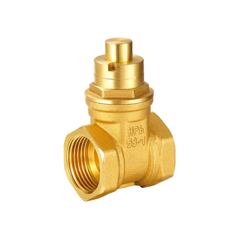
YH-101 Magnetic Lockable Brass Gate Valve
-
 View More
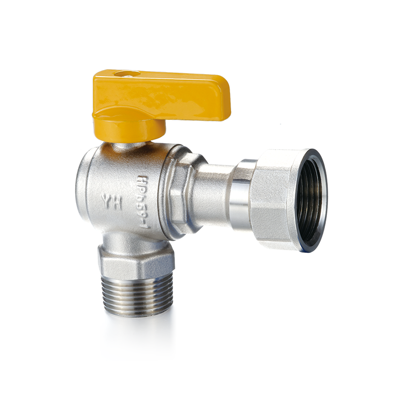
YH-215 Brass Right Angle Ball Valve(F/M)
-
 View More
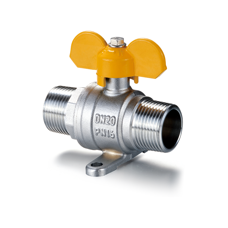
YH-214 Brass Ball Valve with Base& Butterfly Handle(M/M)
-
 View More
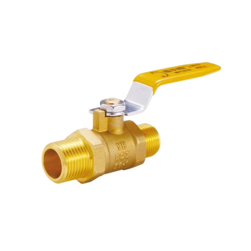
YH-221 Brass Ball Valve with Long Handle(M/M)
-
 View More
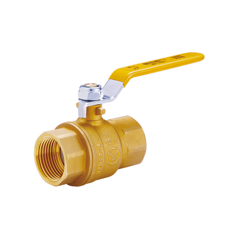
YH-220 Full Port Brass Ball Valve with Long Handle(F/F)
Related News
Contact Us
-

-
 +86-0574-63742169
-
 No.104-128, Cizhang East Road, Zhangqi Town, Cixi City, Ningbo, Zhejiang Province, China


Message Us Now !
