


 English
  русский
  عربى
عربى  Español
Lockable Brass Ball Valve for Secure, High-Flow Fluid Control
Content
- 1 Product Overview
- 2 Why Lockable Control Matters
- 3 Visual Lock Status Indication
- 4 Full-Port Flow Performance
- 5 Brass Body Construction
- 6 Pressure and Temperature Capability
- 7 Threaded F/F Connection and ISO 228 Compatibility
- 8 Advantages Compared with Conventional Ball Valves
- 9 Commercial Building Utility Control
- 10 Industrial Process Pipelines
- 11 Public Facility Water and Gas Management
- 12 Manufacturing Strengths
- 13 Quality Control from Machining to Testing
- 14 Installation Recommendations
- 15 Operation and Maintenance
- 16 Selection Guide for Project Engineers
- 17 How the Product Supports Total Cost Management
- 18 Responsible Use and Application Limits
- 19 Manufacturer Capability and Customer Support
- 20 Frequently Asked Questions
- 20.1 What type of valve is the YH-218?
- 20.2 What does F/F mean?
- 20.3 What pressure can the valve handle?
- 20.4 What temperatures are suitable for the product?
- 20.5 Which media can pass through the valve?
- 20.6 What is the benefit of the lockable mechanism?
- 20.7 How does the visual indicator help?
- 20.8 Is the valve suitable for flow regulation?
- 20.9 What sizes are available?
- 20.10 What thread standard does the valve use?
- 20.11 Can the valve be used outdoors?
- 20.12 Does the lockable feature replace a formal lockout procedure?
- 20.13 Why is the full-port design useful?
- 20.14 What manufacturing resources support the product?
- 20.15 How should the valve be maintained?
- 21 Conclusion
- 22 References
- 23 Product: YH-218 Lockable Ball Valve(F/F)
Modern commercial buildings, industrial facilities, utility networks, and public infrastructure require valve solutions that do more than start or stop fluid flow. In many installations, an operator must also prevent unauthorized adjustment, make the operating condition immediately visible, and maintain dependable performance under pressure. The YH-218 Lockable Ball Valve with female-to-female threaded connections is designed to address these requirements in one compact brass valve assembly.
Combining a full-port flow path, a robust brass body, dual-control locking functionality, and a visual lock-status indicator, the YH-218 provides practical control for water, non-corrosive fluids, and gas systems. Its design is particularly useful where several people may access the same utility installation but only approved personnel should be able to change the valve position. The valve can be operated manually when access is authorized and secured against unwanted operation when the line needs to remain in a controlled condition.
This article examines the valve’s construction, operating advantages, connection standard, pressure and temperature capabilities, application value, and manufacturing background. It also explains why a lockable full-port brass ball valve can be a more effective choice than a conventional unprotected shutoff valve in commercial and industrial environments.
Product Overview
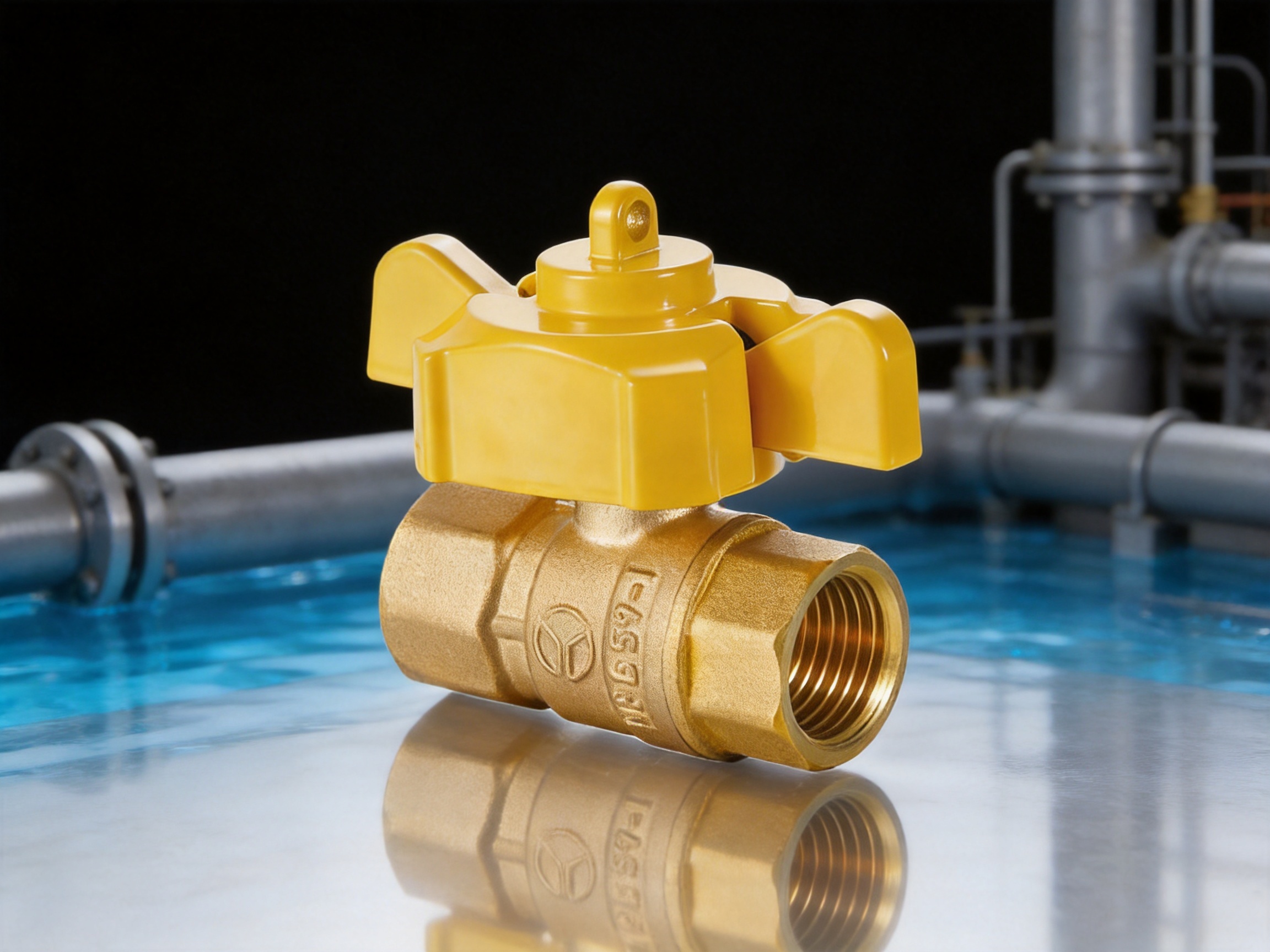
The YH-218 belongs to the brass lockable ball valve category and uses female-to-female, or F/F, threaded connections. It is available in DN15 and DN20 sizes, corresponding to 1/2-inch and 3/4-inch nominal thread sizes. The parallel pipe threads comply with ISO 228, supporting compatibility with appropriately specified threaded pipework, fittings, and equipment.
The valve is rated for a nominal pressure of 1.6 MPa. Its stated working media include water, non-corrosive fluids, and gas, while its working temperature range is from -20°C to below 80°C. These specifications make the product suitable for a wide range of building utility systems and selected industrial service applications, provided that the installation conditions, fluid compatibility, and applicable safety requirements are properly evaluated.
| Product Attribute | Specification |
| Product model | YH-218 |
| Valve type | Lockable brass ball valve |
| Connection | Female-to-female threaded connection |
| Thread standard | Parallel pipe thread to ISO 228 |
| Nominal pressure | 1.6 MPa |
| Working media | Water, non-corrosive fluids, and gas |
| Working temperature | -20°C to below 80°C |
| Available nominal sizes | DN15 and DN20 |
| Primary functions | Shutoff, manual operation, lockable control, and visual status indication |
The product is intended to provide straightforward on-off control rather than throttling regulation. In a ball valve, a drilled ball rotates inside the valve body. When the bore is aligned with the pipeline, the valve is open and fluid can pass through the full internal passage. When the ball rotates ninety degrees, the bore is positioned across the flow path and the valve closes. This simple quarter-turn principle allows rapid operation and makes the valve easy to understand during inspection.
Why Lockable Control Matters
A conventional ball valve can usually be turned by anyone who can reach its handle. That may be acceptable in a private installation with limited access, but it creates avoidable risks in shared facilities. A cleaner, a tenant, a contractor, or an untrained visitor may unintentionally change the position of a valve serving a gas line, water supply, process branch, or emergency utility circuit. A lockable valve introduces a physical control point that helps facility managers restrict operation to authorized personnel.
The YH-218 uses a dual-control locking mechanism. This arrangement balances accessibility and security instead of forcing every user into one operating mode. When the valve is authorized for operation, the handle can be used manually in the normal way. When the valve must remain in a defined position, the locking function can be engaged so that unauthorized users cannot freely change the setting.
This approach is valuable during maintenance, commissioning, shutdown, equipment isolation, and routine property management. For example, a building manager may need to keep a branch water line closed while a pipe repair is in progress. An industrial supervisor may need to ensure that a gas supply remains isolated until a work permit has been completed. A public facility may need to prevent visitors from opening or closing a service valve located in an accessible mechanical room. In each case, a lockable mechanism provides an additional layer of procedural control.
The locking feature does not replace safe work procedures, pressure relief, isolation verification, or legally required gas safety measures. Instead, it supports those procedures by making the selected valve position more difficult to alter accidentally or casually. The product therefore contributes to operational discipline as well as basic fluid control.
Visual Lock Status Indication
One of the practical strengths of the YH-218 is its visual lock-status indicator. A valve may be physically secure, but if its status is not obvious, inspection can still be slow or confusing. Maintenance personnel often need to assess several valves in a short period of time, sometimes in restricted spaces or under imperfect lighting. A clear visual indication helps them identify whether the valve is locked or unlocked without unnecessary handling.
Visual status information is especially useful in facilities with shift-based operations. A technician beginning a shift can quickly review the condition of critical utility points. A supervisor checking a work area can identify whether a valve remains under controlled access. During maintenance handover, a visible indication reduces the possibility that one team will assume a valve is available for operation when another team has secured it.
The indicator also supports better documentation. When valve positions and lock conditions are recorded during inspection, personnel can compare the physical indication with the maintenance log or isolation plan. If the observed condition does not match the record, the discrepancy can be investigated before work begins.
In this way, the YH-218 is not simply a shutoff device. It is a communication tool within a fluid-control system. Its mechanical position, lock condition, and operating purpose can be understood more quickly, helping improve the efficiency of routine inspection and facility management.

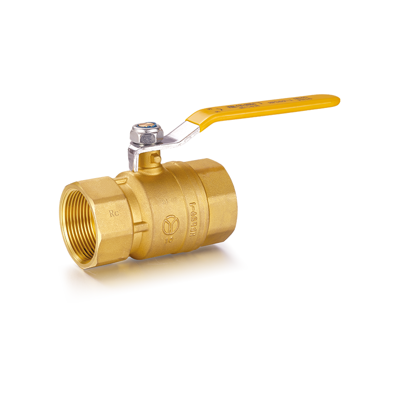
YH-218 Lockable Ball Valve(F/F)
Full-Port Flow Performance
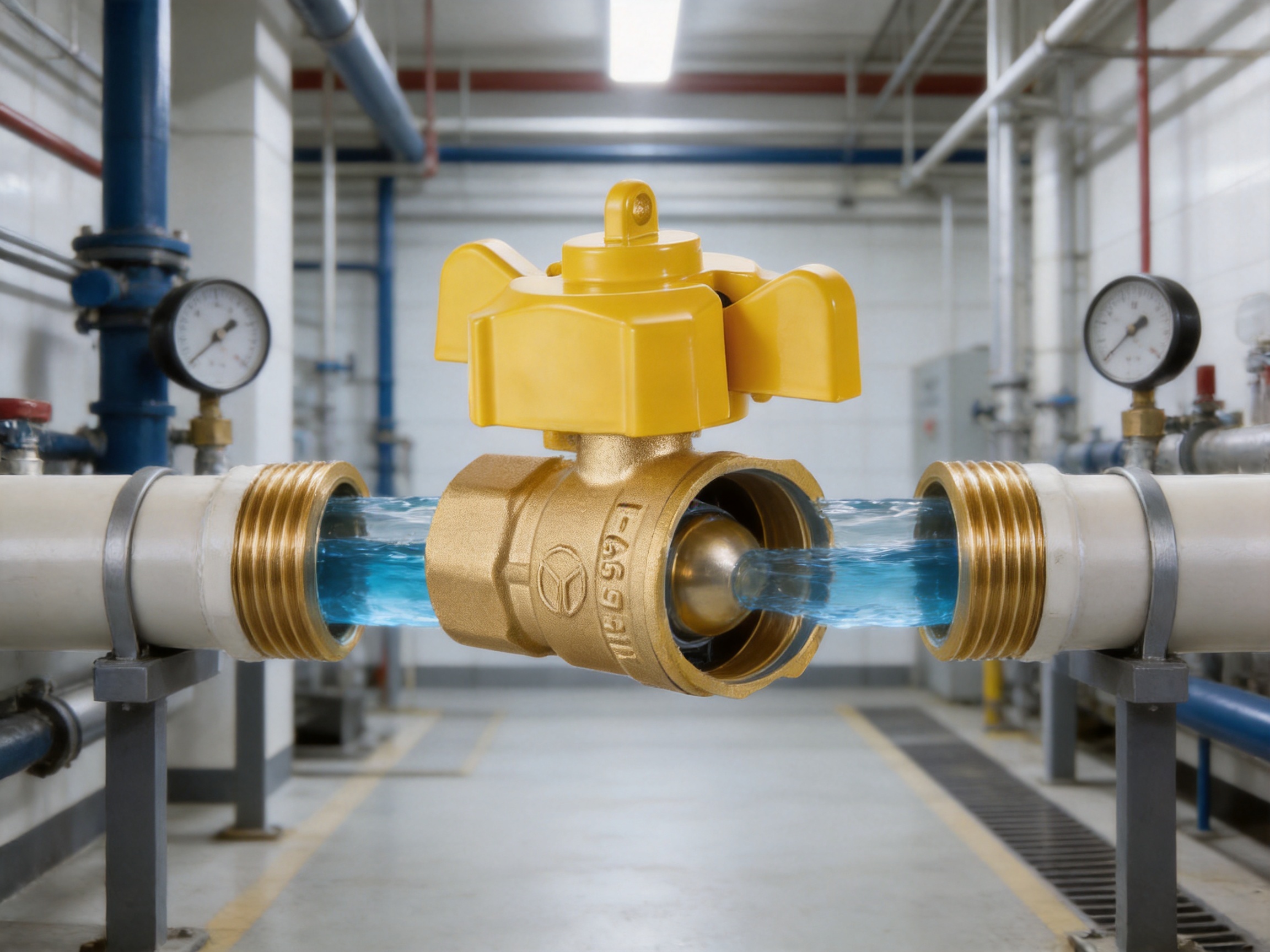
The YH-218 uses a full-port design. The internal passage through the ball is designed to maintain a flow area close to the connected pipe bore, minimizing unnecessary restriction when the valve is fully open. This characteristic is important in systems where the available flow rate, pressure drop, or pumping energy must be carefully managed.
Compared with a reduced-port valve of the same nominal connection size, a full-port valve can offer a more direct flow path. The reduction in internal obstruction can help limit turbulence and pressure loss across the open valve. This is beneficial in water distribution, gas supply branches, equipment connections, and process lines where the valve should have limited influence on the normal operating flow.
Full-port construction also provides practical advantages during maintenance. The relatively open passage is less likely to create a narrow internal throat that collects certain forms of debris. However, no valve should be treated as immune to contamination. Pipework should be cleaned and flushed appropriately before commissioning, and strainers or filtration should be used when required by the system design.
The full-port configuration is particularly valuable when a valve is installed upstream of equipment that depends on adequate flow. Examples include water heaters, pumps, fire-related auxiliary systems, gas appliances, and process machinery. The correct valve selection must still consider the total system design, but a full-port ball valve provides a strong starting point where low flow resistance is preferred.
Brass Body Construction
Brass is widely used for compact fluid-control valves because it combines practical strength, machinability, corrosion resistance in many common environments, and reliable sealing compatibility. The brass body of the YH-218 provides a solid housing for the ball, seats, stem, and threaded connection sections. It is intended for water, non-corrosive fluids, and gas service within the stated operating limits.
A brass body is also well suited to precision machining. Its material characteristics allow threaded sections and internal sealing surfaces to be manufactured with controlled dimensions. Accurate machining is essential for creating a secure connection, maintaining smooth ball movement, and supporting dependable sealing around the stem and ball.
The body material contributes to the valve’s suitability for building services and general utility applications. It offers a practical balance between durability and compact size, allowing the valve to be installed in cabinets, service shafts, equipment rooms, plant areas, and other locations where space is limited.
Material selection must always be matched to the fluid. The YH-218 is described for water, non-corrosive fluids, and gas, but users should verify the compatibility of every wetted component with the specific medium, additives, pressure, and temperature. Aggressive chemicals, oxygen service, high-temperature fluids, or other specialized media may require a different valve design and dedicated approval.
Pressure and Temperature Capability
The YH-218 has a nominal pressure rating of 1.6 MPa. This rating indicates that the valve is designed for demanding water, gas, and general utility applications within the applicable operating conditions. The pressure rating should not be considered separately from temperature, fluid type, connection quality, installation practice, and relevant local standards.
In an operating system, pressure may vary because of pump operation, regulator settings, thermal expansion, water hammer, compressor behavior, or process changes. A valve selected for a 1.6 MPa nominal pressure should be installed in a system where the actual pressure, including foreseeable transient conditions, remains within the permitted limits. Pressure gauges, relief devices, regulators, and isolation procedures should be used when required by the system design.
The working temperature range is specified as -20°C to below 80°C. This allows the valve to serve many indoor and outdoor utility installations, including cold-water lines, ambient-temperature process branches, and selected gas systems. The lower limit supports use in cold environments, while the upper limit accommodates common building and utility conditions without positioning the product as a high-temperature industrial valve.
Temperature can affect sealing materials, pressure capability, fluid behavior, and installation safety. Users should therefore confirm that the full assembly is appropriate for the intended temperature and that the medium will not freeze or expand in a way that damages the valve. Outdoor installations may also require insulation, protection from impact, and measures against frost or excessive solar heating.
Threaded F/F Connection and ISO 228 Compatibility
The female-to-female connection arrangement gives the YH-218 a familiar and adaptable installation format. Both ends accept compatible male-threaded pipe, nipples, adapters, or equipment connections. This configuration is convenient for many building and utility layouts because the valve can be installed between two externally threaded components without requiring a special proprietary interface.
The parallel pipe thread is manufactured to ISO 228. A standardized thread form helps users select compatible components and supports consistent installation practices. It is still essential to distinguish parallel pipe threads from tapered thread systems. The installer should confirm the thread type, sealing method, fitting material, and local plumbing or gas requirements before assembly.
Threaded connections should be aligned carefully. Excessive force, cross-threading, contaminated threads, or unsupported pipework can damage the valve or produce leakage. Sealant or sealing tape should be selected according to the medium and applicable regulations. For gas installations, only approved sealing products and procedures should be used, and the completed system must be tested for leakage according to local requirements.
The F/F design also supports replacement and serviceability. If a valve eventually needs to be changed, a threaded connection can allow removal without cutting a long section of pipe, provided that the surrounding installation has been designed with sufficient access and suitable isolation points. This can reduce service time and simplify future modifications.
| Size | Thread Size, G | Internal Dimension, D | Overall Length, L | Height, A |
| DN15 | 1/2 inch | 12 | 55 | 43.5 |
| DN20 | 3/4 inch | 18 | 66 | 48 |
The dimensions provide a basis for planning valve placement, pipe routing, cabinet space, and maintenance clearance. Actual installation drawings should account for the handle movement, locking access, pipe supports, insulation thickness, and the tools needed for tightening or inspection.
Advantages Compared with Conventional Ball Valves
The most important advantage of the YH-218 over a basic non-lockable ball valve is controlled access. A standard handle provides a simple on-off function, but it generally does not communicate whether the valve has been intentionally secured. The YH-218 adds a locking function and a visible status indication, which are highly relevant in shared or regulated environments.
A second advantage is the combination of security and normal manual operation. Some specialized isolation arrangements may require separate lockout equipment or additional accessories before a valve can be secured. The integrated dual-control mechanism is intended to make the operation more direct. Authorized users can operate the valve, while managers can restrict access when the operating position must be preserved.
A third advantage is the full-port flow path. Certain compact valves may reduce the internal passage, increasing resistance in the open condition. The YH-218 is designed for systems where maintaining a generous flow path is important. This can be beneficial in applications where the valve is opened for long periods and should not unnecessarily reduce the performance of the connected line.
A fourth advantage is the practical material and pressure combination. A brass body rated at 1.6 MPa offers a useful balance for commercial water, gas, and general utility systems. The product is more substantial than a light-duty valve intended only for low-pressure service, while remaining compact enough for common threaded installations.
Another advantage is inspection efficiency. A visible lock indicator can reduce the need for repeated physical testing of the handle. This does not eliminate the need to verify isolation when safety depends on it, but it can make routine rounds, handovers, and maintenance checks faster and more consistent.
These advantages are most meaningful when the product is matched to the correct application. A lockable brass ball valve is not automatically the best solution for every fluid, temperature, pressure, or regulatory environment. Its strength lies in combining secure access control, clear status communication, full flow, and practical threaded installation for the service conditions identified by the manufacturer.
Commercial Building Utility Control
Commercial buildings contain extensive networks of water, gas, heating, cooling, and equipment supply lines. Many of these lines pass through shared mechanical rooms, service corridors, ceiling voids, or tenant areas. A valve that can be operated by anyone may create operational problems when access control is important.
The YH-218 can be used at selected branch points where building managers need to isolate a tenant supply, control a maintenance zone, or secure a utility circuit after working hours. Its compact threaded format is suitable for many small-diameter branches, while the full-port design helps preserve flow when the valve is open.
In a retail property, for example, the valve may be installed on a water branch serving a shop or food-service area. In an office building, it may control a local utility connection within a plant room. In a residential or mixed-use project, it may support organized access to individual water or gas service points, subject to the relevant installation codes and approval requirements.
The visual indicator can also support facility asset management. Valves can be labeled according to zone, equipment, or tenant, and their lock status can be reviewed during planned inspections. When combined with an updated piping schematic and maintenance schedule, the valve helps transform a hidden pipe component into a clearly managed utility asset.
Industrial Process Pipelines
Industrial environments often require frequent isolation of small process branches, instrument supplies, utility lines, and service connections. The ability to lock a valve in a selected position can help prevent accidental adjustments during production, cleaning, inspection, or repair.
The YH-218 is suitable for water and non-corrosive fluid applications within its pressure and temperature range. It may be considered for utility water, compressed or regulated gas service where approved, equipment cooling branches, and other general-purpose process support lines. Engineers should assess chemical compatibility and process hazards before specifying the valve.
In a production facility, multiple teams may work around the same piping network. Operators, maintenance technicians, contractors, and safety personnel may each have different responsibilities. A visible lock condition provides useful information during coordination. The valve can be included in an isolation plan, marked on a line diagram, and reviewed during permit-to-work procedures.
The quarter-turn ball mechanism is also advantageous in situations where rapid shutoff is required. A long series of wheel rotations is unnecessary; the operator can move the valve between open and closed positions using a short handle rotation. The locking function then helps preserve the selected state until authorized operation is required.
Public Facility Water and Gas Management
Public facilities such as schools, sports centers, transport buildings, hospitals, and community centers may contain utility valves in areas that are not continuously supervised. In these settings, accidental or unauthorized operation can interrupt service or create a safety concern.
A lockable valve can be used at controlled service points, maintenance zones, plant rooms, and equipment connections. The visual indicator helps staff understand whether a valve is available for operation or under restricted control. This is particularly useful when personnel who are not valve specialists need to identify the status of a system during routine checks.
For gas applications, the valve must be installed only where the complete product specification, local regulations, and project approvals permit its use. Gas systems require suitable materials, leak testing, ventilation, emergency procedures, and qualified installation. The lockable feature is an operational aid, not a substitute for certified gas-system design or emergency shutoff provisions.
For water management, the valve can help divide a large facility into manageable service zones. A maintenance team may isolate one area without shutting down the entire building. The full-port passage helps limit the effect of the valve on normal supply flow, while the threaded design facilitates installation in appropriately sized branches.
Manufacturing Strengths
The performance of a precision valve depends not only on its design but also on how consistently that design is manufactured. Ningbo Yunhua Valve Co., Ltd. operates as an integrated manufacturer specializing in gas and fluid valves, water supply valves, and hardware accessories. Its activities include research and development, production, sales, and service.
The company has developed its manufacturing capabilities over more than ten years of operation. During this period, it has worked to improve its management system, establish a professional management team, and develop a corporate culture focused on reliable fluid-control products. This combination of technical development and organizational structure supports repeatable production rather than reliance on isolated manual practices.
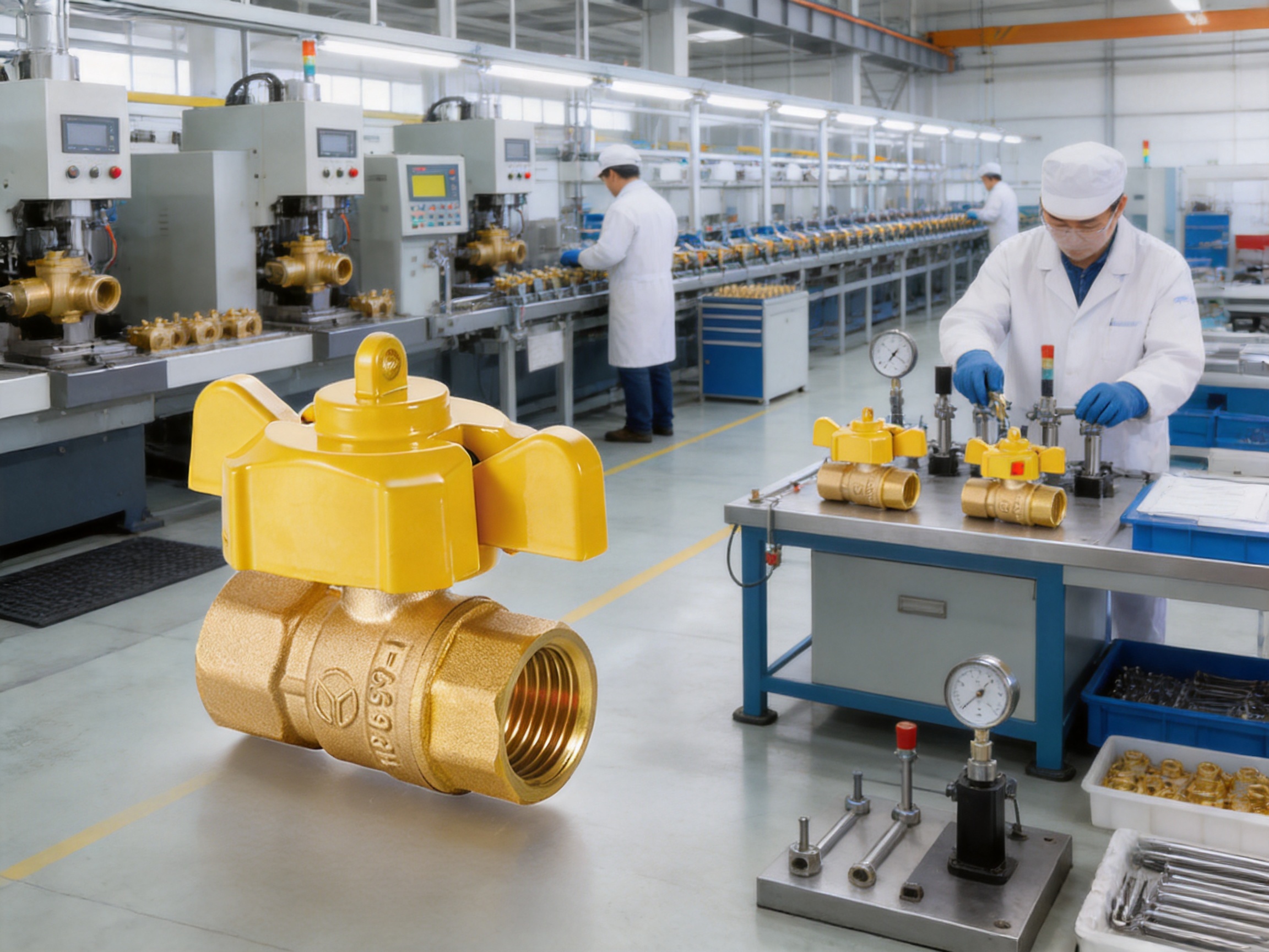
The company covers approximately 20,000 square meters and has established a precision machining workshop, assembly line, and testing workshop. The presence of dedicated areas for machining, assembly, and testing provides a structured production route for valve components. It also creates opportunities to control quality at several stages instead of waiting until the final product inspection.
Precision machining is particularly important for the YH-218. The body must maintain accurate connection dimensions, internal geometry, and sealing interfaces. The stem and ball require suitable dimensional control to support smooth quarter-turn movement and reliable shutoff. Thread quality must also be managed carefully so that the valve can be installed with compatible fittings without excessive force or misalignment.
The company is equipped with domestic and international CNC machine tools. CNC equipment supports repeatability by using controlled machining programs and defined tooling processes. It can help produce consistent batches of brass bodies and other components while reducing variation between individual units. For a threaded valve, this consistency is important because even small dimensional deviations can affect assembly, connection fit, or sealing performance.
Automated assembly and testing equipment further strengthens the production process. Automation can improve repeatability in operations such as component placement, tightening, and functional checking. It can also help establish more consistent production records and reduce dependence on subjective manual judgment.
The company reports an annual production capacity of approximately 2 million sets of valves and 10 million sets of hardware accessories. This capacity indicates that the manufacturer is organized to support volume requirements as well as standard product supply. For distributors, contractors, and original equipment customers, manufacturing scale can be important when consistent replenishment, delivery planning, and product continuity are required.
Quality Control from Machining to Testing
Quality control for a lockable ball valve should cover the entire product life cycle, beginning with material preparation and continuing through machining, cleaning, assembly, pressure testing, functional checking, and packaging. A valve that looks satisfactory externally may still have problems if its threads, sealing surfaces, locking components, or internal passage are not properly controlled.
At the machining stage, inspection can focus on body dimensions, thread geometry, port alignment, and surface condition. The aim is to ensure that parts remain within the defined manufacturing requirements. Proper control of these characteristics supports smooth assembly and reduces the risk of leakage or difficult installation.
During assembly, the ball, stem, seats, seals, handle, and locking mechanism must be installed in the correct relationship. The ball must rotate reliably between the open and closed positions. The stem must transmit handle movement without excessive play. Sealing components must be seated properly, and the lock-status indicator must correspond to the intended operating condition.
Testing provides another essential control point. Depending on the applicable internal procedures and project requirements, testing may include body pressure testing, seat leakage testing, operational cycling, thread inspection, and visual examination. The stated 1.6 MPa nominal pressure rating should be supported by appropriate manufacturing verification and by correct installation in the field.
Functional testing is especially significant for this product because it has more than a basic shutoff function. The valve should be checked not only for opening and closing but also for the operation of its locking mechanism and the clarity of its visual status indication. A lockable valve that cannot be operated smoothly or whose indicator is unclear would not deliver the full value of its design.
Testing workshops allow these activities to be organized in a controlled environment. When inspection and testing are integrated into the manufacturing workflow, defects can be identified before products reach customers. This supports more dependable installation outcomes and reduces the possibility of field rework.
Installation Recommendations
Before installation, confirm the valve model, size, thread type, pressure rating, temperature range, and working medium. Verify that the pipework uses compatible ISO 228 parallel threads or appropriate matching components. Check that the valve has not been damaged during transport and that the locking mechanism and handle move correctly before the valve is connected to the system.
Pipework should be clean, correctly aligned, and adequately supported. The valve should not be used to compensate for misaligned pipes. If the pipe ends are forced into alignment by tightening the valve, mechanical stress may be transferred to the body and connections. Such stress can affect sealing, operation, and long-term durability.
Use a suitable thread-sealing method for the service. Sealant should be applied carefully so that it does not enter the valve bore or interfere with the ball and seats. For gas service, the sealing product and installation procedure must comply with local requirements and the recommendations of the responsible engineer or authority.
Use the correct tools on the appropriate connection surfaces. Avoid gripping or striking the handle, locking parts, or other operating components while tightening the threaded connections. Excessive torque can damage threads or distort the body. After installation, operate the valve through its full range and confirm that the indicator corresponds to the actual condition.
Install the valve where the handle and lock-status indicator remain accessible. A lockable valve cannot provide its intended management benefit if it is hidden behind permanent structures, buried under insulation, or positioned so tightly against adjacent equipment that authorized personnel cannot inspect or operate it.
After commissioning, test the system for leakage and verify the valve position under operating conditions. Gas installations require particular attention to approved testing methods, ventilation, ignition control, and emergency procedures. The valve should be included in the facility’s line identification, maintenance records, and isolation documentation.
Operation and Maintenance
The YH-218 is designed for quarter-turn on-off operation. Move the handle deliberately between the open and closed positions rather than leaving it partially open for prolonged throttling service. Ball valves generally provide their best performance when used as isolation devices. Continuous throttling may increase wear, turbulence, and seat stress beyond the intended operating pattern.
Before operating the valve, confirm that authorization has been given and that changing the valve position will not endanger personnel, equipment, or production. Check pressure conditions where appropriate. If the valve is locked, follow the site’s authorization and lock-control procedure rather than attempting to force the handle.
Routine inspection should include checking for external leakage, corrosion, physical damage, loose connections, restricted access, and signs of unauthorized operation. The locking mechanism should be examined to confirm that it engages and releases correctly. The visual indicator should remain legible and should accurately represent the lock status.
Where the valve is installed outdoors or in a corrosive atmosphere, the surrounding environment should be reviewed regularly. Protective measures may be necessary in areas exposed to salt, chemicals, impact, flooding, freezing, or extreme weather. Although brass is suitable for many common environments, no material is appropriate for every exposure condition.
Maintenance intervals should be based on the importance of the service, operating frequency, fluid cleanliness, environmental conditions, and the facility’s risk assessment. If abnormal resistance, leakage, or uncertain status is found, the line should be isolated safely and the valve assessed by qualified personnel. Do not continue operating a damaged or leaking valve merely because it still turns.
Selection Guide for Project Engineers
When specifying the YH-218, begin by identifying the medium. The product is intended for water, non-corrosive fluids, and gas, but the actual fluid composition should be reviewed. For water, consider additives, hardness, suspended solids, and temperature. For gas, consider the gas type, pressure, regulatory requirements, and sealing compatibility. For process fluids, verify that every wetted material is chemically suitable.
Next, confirm the required connection size. DN15 corresponds to a 1/2-inch connection, while DN20 corresponds to a 3/4-inch connection. The internal and overall dimensions should be compared with the available pipe space. Engineers should also allow room for handle movement, lock access, inspection, and future replacement.
Pressure and temperature must be evaluated together. The nominal pressure is 1.6 MPa, and the working temperature is -20°C to below 80°C. The system’s maximum working pressure, pressure surges, minimum temperature, and maximum temperature should all remain within the applicable limits. If the application approaches the boundary of these specifications, professional technical confirmation is advisable.
Finally, decide whether the locking function provides a meaningful operational benefit. It is particularly valuable when unauthorized adjustment is possible, when multiple groups share the facility, or when maintenance isolation must be clearly controlled. If a standard valve would be freely accessible but the system requires restricted operation, the YH-218 offers a more complete solution.
How the Product Supports Total Cost Management
Product cost is only one part of the economic evaluation of a valve. Installation time, inspection effort, unplanned shutdowns, replacement frequency, and the consequences of unauthorized operation can have a greater effect on the total cost of ownership. The YH-218 addresses several of these factors through its integrated design.
The threaded F/F configuration can simplify installation in small-diameter branches and make future replacement more manageable. The full-port passage can help maintain system performance when the valve is open. The lockable mechanism can reduce the risk of avoidable service interruptions caused by casual or accidental operation. The visual indicator can reduce the time needed to review valve status during routine rounds.
A valve that clearly communicates its status can also improve maintenance planning. Technicians can identify controlled points more quickly, organize work permits more effectively, and reduce uncertainty during shift handover. These operational improvements may not appear in the purchase price, but they can contribute to lower labor and downtime costs over the service life of the installation.
Reliable manufacturing is another component of value. Ningbo Yunhua Valve Co., Ltd. combines CNC machining, automated assembly, and dedicated testing facilities with substantial production capacity. For customers purchasing repeated quantities, consistency between batches is important because it supports standardized installation procedures, spare-parts planning, and maintenance training.
Responsible Use and Application Limits
The YH-218 should be selected and installed according to the actual risk level of the system. It is intended for general fluid-control applications identified in the product information. It should not be assumed to be suitable for steam, highly corrosive chemicals, abrasive slurries, oxygen service, cryogenic media, or other specialized conditions without explicit technical confirmation.
For gas service, local laws and codes may require specific product approvals, installation methods, pressure testing, ventilation, emergency shutoff arrangements, and inspection procedures. The installer and system designer remain responsible for ensuring that the complete installation meets those requirements.
The lockable mechanism is an aid to access management. It does not guarantee zero leakage through a closed valve, nor does it replace positive isolation where hazardous work is being performed. When personnel safety depends on isolation, the system should be depressurized, drained or vented as appropriate, and verified using the required procedures and equipment.
Correct application is the foundation of reliable performance. When the medium, pressure, temperature, connection standard, and operational purpose match the product specifications, the YH-218 can provide a practical combination of secure control, clear inspection, and efficient flow.
Manufacturer Capability and Customer Support
Ningbo Yunhua Valve Co., Ltd. describes itself as an innovative enterprise focused on gas and fluid valves, water supply valves, and hardware accessories. Its business scope covers research and development, manufacturing, sales, and service, allowing it to support products through multiple stages of their commercial life.
The company’s management development over more than a decade is relevant to product reliability. A professional management system helps coordinate purchasing, production planning, machining, assembly, inspection, warehousing, and customer service. This structure is especially important for valve products because quality depends on the interaction of many small components and process steps.
The 20,000-square-meter facility provides space for precision machining, automated assembly, and testing operations. Advanced CNC machine tools support accurate production of valve bodies and components. Automated equipment helps standardize assembly and testing. Together, these capabilities are intended to support stable quality and efficient output.
The reported annual capacity of 2 million valve sets and 10 million hardware accessory sets demonstrates the company’s ability to serve both standard distribution and larger project demand. Capacity alone does not define quality, but it can provide the manufacturing infrastructure needed for regular supply, production continuity, and consistent product availability.
The company’s stated vision is to become a leading participant in the global fluid-control industry, while its mission is to build a safe fluid ecosystem through high-quality valves. The YH-218 reflects that direction by combining basic shutoff performance with access management and status visibility. These features are closely related to the broader goal of making fluid systems safer and easier to control.
Frequently Asked Questions
What type of valve is the YH-218?
The YH-218 is a lockable brass ball valve with female-to-female threaded connections. It is designed for quarter-turn on-off control of water, non-corrosive fluids, and gas within the stated operating limits.
What does F/F mean?
F/F means female-to-female. Both ends of the valve have internal threads, allowing connection to compatible male-threaded pipe, fittings, nipples, or equipment ports.
What pressure can the valve handle?
The stated nominal pressure is 1.6 MPa. The actual installation must remain within the applicable pressure limits, including any pressure surges, and must also satisfy the temperature and medium requirements.
What temperatures are suitable for the product?
The working temperature range is -20°C to below 80°C. Applications outside this range require a different product or specific technical confirmation.
Which media can pass through the valve?
The listed working media are water, non-corrosive fluids, and gas. Users should verify the chemical compatibility of the specific medium and all wetted components before installation.
What is the benefit of the lockable mechanism?
The mechanism helps authorized personnel operate the valve while restricting unwanted or unauthorized changes to its position. It is useful for maintenance isolation, building utility management, industrial process support, and public facility control.
How does the visual indicator help?
The visual indicator shows whether the valve is locked or unlocked. This makes routine inspection, maintenance handover, and facility management easier because personnel can understand the lock condition more quickly.
Is the valve suitable for flow regulation?
The YH-218 is primarily an on-off isolation valve. Its full-port design is intended to provide a relatively open flow path when fully open. Prolonged throttling should be avoided unless the application has been specifically evaluated and approved.
What sizes are available?
The available sizes listed for the product are DN15 and DN20. DN15 uses a 1/2-inch G connection, while DN20 uses a 3/4-inch G connection.
What thread standard does the valve use?
The product uses parallel pipe threads to ISO 228. The installer should confirm compatibility with the mating pipe and select an appropriate sealing method.
Can the valve be used outdoors?
It may be suitable for outdoor use when the pressure, temperature, medium, and environmental conditions remain within the application requirements. Outdoor installations should be protected against freezing, impact, flooding, severe corrosion, and other site-specific hazards.
Does the lockable feature replace a formal lockout procedure?
No. The feature supports access control but does not replace formal lockout, tagout, depressurization, verification, or permit-to-work procedures. Safety-critical isolation must follow the requirements of the responsible facility and applicable regulations.
Why is the full-port design useful?
A full-port design provides a generous internal passage when the valve is open. This can reduce unnecessary flow restriction and is useful in systems where maintaining flow capacity and limiting pressure loss are important.
What manufacturing resources support the product?
The manufacturer operates precision machining, assembly, and testing workshops and uses CNC machine tools together with automated assembly and testing equipment. These resources support dimensional consistency, repeatable assembly, and product verification.
How should the valve be maintained?
Inspect the valve for leakage, corrosion, damage, difficult operation, loose connections, and unclear lock status. Keep the valve accessible, operate it only when authorized, and have qualified personnel assess any abnormal condition.
Conclusion
The YH-218 Lockable Ball Valve provides a practical answer to a common challenge in modern fluid systems: how to combine dependable shutoff with controlled access and clear operational information. Its brass body, 1.6 MPa nominal pressure rating, full-port passage, ISO 228 parallel threads, and compact F/F configuration support a broad range of water, non-corrosive fluid, and gas applications.
Its strongest distinction is the integration of dual-control locking and visual lock-status indication. These features make the valve more suitable than a basic non-lockable ball valve for commercial buildings, industrial process support lines, public facilities, and shared utility systems where unauthorized operation could cause disruption or risk.
The product is also supported by a manufacturing organization with precision CNC machining, automated assembly, dedicated testing workshops, professional management, and substantial annual production capacity. These capabilities help create a foundation for consistent supply and repeatable product quality.
When correctly selected, installed, tested, and maintained, the YH-218 can contribute to safer facility management, easier inspection, efficient flow, and more disciplined control of utility and process lines. Its value comes not from one feature alone, but from the way secure operation, full-port performance, brass construction, standardized connections, and organized manufacturing work together in a single valve solution.
References
1. Product information supplied for the YH-218 Lockable Ball Valve, including pressure, temperature, medium, dimensional, and connection specifications.
2. ISO 228, Pipe Threads Where Pressure-Tight Joints Are Not Made on the Threads.
3. General engineering principles for quarter-turn ball valve operation, threaded fluid connections, and valve maintenance.
4. General facility safety practices for valve identification, access control, isolation, inspection, and maintenance handover.
5. Manufacturer-provided company information concerning precision machining, automated assembly, testing facilities, production capacity, and fluid-control product development.
Product: YH-218 Lockable Ball Valve(F/F)

Related Products
-
 View More
-
 View More
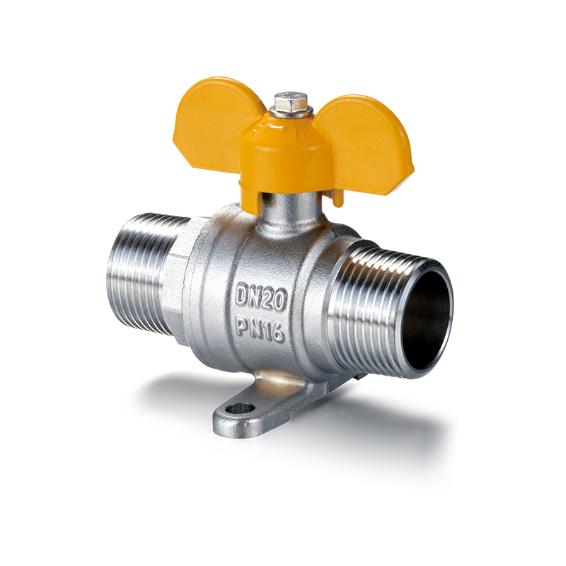
YH-214 Brass Ball Valve with Base& Butterfly Handle(M/M)
-
 View More
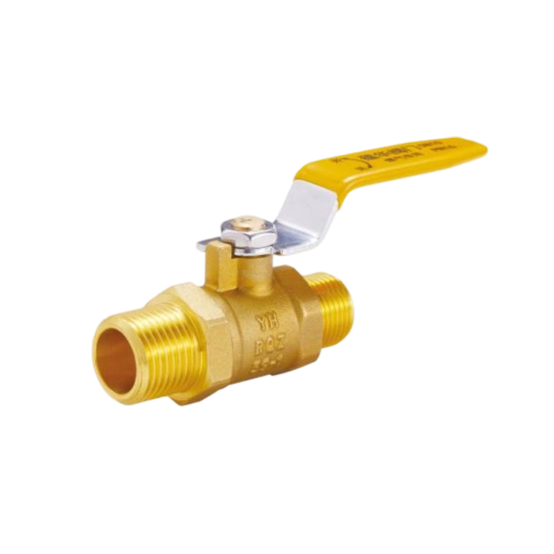
YH-221 Brass Ball Valve with Long Handle(M/M)
-
 View More
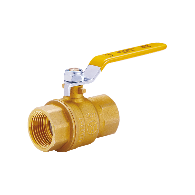
YH-220 Full Port Brass Ball Valve with Long Handle(F/F)
-
 View More
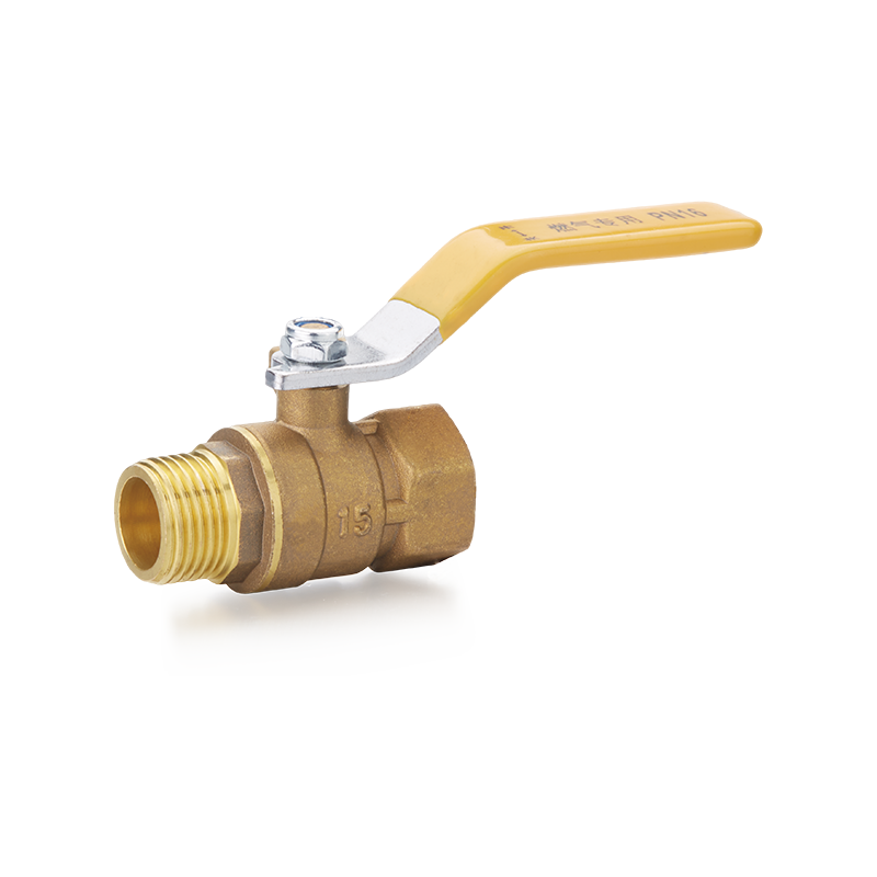
YH-202 Brass Ball Valve with Long Handle(F/M)
-
 View More
YH-201 Brass Ball Valve with Long Handle(F/F)
Related News
Contact Us
-

-
 +86-0574-63742169
 -
 No.104-128, Cizhang East Road, Zhangqi Town, Cixi City, Ningbo, Zhejiang Province, China


Message Us Now !
